Tubo de Extensión
Tuerca de Ajuste de
Altura
Base
ENSAMBLE DEL PIE
COLOQUE LA BASE EN EL PISO
1. Con un movimiento rápido, inserte el extremo de la tubería de
gran diámetro en el agujero en la base. (Figura 5) En cuanto la
tubería mientras se empuja asegurará la tubería esté
completamente asentado en la base.
2. Para ajustar la altura:
a) Afloje la Tuerca de Ajuste de Altura.
b) Eleve o baje el Tubo de Extensión hasta obtener la altura
deseada.
c) Apriete la Tuerca de Ajuste de Altura.
MODEL S18965
Rev. C 12/16
4
2084847
Rev. C 12/16
9
2084847
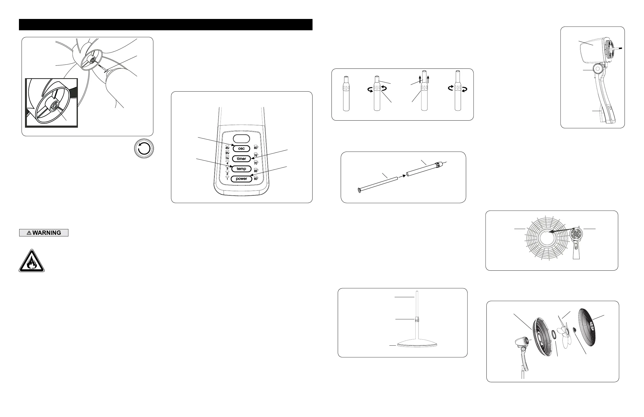
ENSAMBLE DEL ASPAY REJILLA
1. Inclinarla Cabeza del Ventilador hacia atrás. Coloque la Rejilla
Trasera en el Motor. (Figura 7)
2. Alinear la lengüeta de la Rejilla Trasera con la ranura en la parte
superior de la cubierta delantera del Motor.
CONJUNTO DE LA CABEZA
1. Coloque el Conjunto de Ca-
bezal con el Collar en el Tubo
de Extensión. (Figura 6)
2. Sostenga firmemente el Tubo
de Extensión y empuje el Con-
junto de Cabezal hacia abajo
con un movimiento giratorio
hasta que quede asentado en
el Tubo de Extensión.
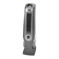
ARMADO DE LA TUBERÍA
1. Saque el conjunto de la tubería del cartón como muestra. (Figura 1)
2. Desafloje la Tuerca de Ajuste de Altura, girando en sentido
contrahorario. (Figura 2)
3. Eleve la Extensión De La Tubería. (Figura 3)
4. Apriete la Tuerca de Ajuste de Altura, girando en sentido horario.
(Figura 4)
3. Asiente la Parrilla Trasera y sujetela con la Tuerca de Plástico
hacia la Derecha. Deslice la Helice en el Eje del Motor.
(Figura 8) Alinear la Ranura Del Cubo de la tapa con el Pasador
del eje del motor. (Figura 8A)
Figura 2
Figura 4Figura 3
Figura 1
Tuerca de
Ajuste de
Altura
Tubería de
Extension
Figura 5
Rejilla
Trasera
Figura 7
Motor
Figura 8
Parrilla Trasera
Helice
Tuerca de
Plastico
Conjunto de
Cabezal
Collar
Tubo de
Extensión
Figura 6
Parrilla
Delantera
Tapa de
Ventilador
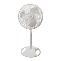
OPERATION
This Fan may be operated by the Controls located on front of
the unit (as shown in Figure 9) or by the Remote Control (shown
in Figure 12).
1. Plug the cord set into a 120 V outlet.
2. Place the Fan on a firm and level surface.
Be sure that the plug fits tightly into outlet.
When plugs fit loosely into receptacles, they may
slip partially or completely out of the receptacle
with only the slight movement of the attached cord.
Receptacles in this condition may overheat and pose
a serious fire hazard; if covered by a curtain or drape,
the fire hazard is even greater.
3. Apply power to the Fan by pushing the Power Button (power).
4. FAN SPEED: You may now adjust the fan speed to the desired
level by pressing the Fan Power Button which will cycle through
the 4 speeds of the fan.
5. OSCILLATION: Press Oscillation Button (osc) to make fan
head move from side to side.
6. TIMER FUNCTION: This fan is equipped with a timer. The
timer can be set for 7 hours. Continue pressing the Timer
Button (timer) to reach the desired time setting. To cancel
timer, press Timer Button (timer) until lights are extinguished.
7. THERMOSTAT FUNCTION: The Thermostat feature senses
the room temperature and turns the Fan on or off automati-
cally as the temperature changes. Press the TEMP button
to select a set temperature – 60°F, 65°F, 70°F, 75°F, 80°F, or
manual mode (below). Your Fan will now turn ON and OFF
at this temperature. The light next to the set temperature
blinks until the room air drops to that temperature. The fan
then turns off and the light becomes solid. The thermostat
can be used in any speed setting.
PRECAUCIÓN:
Cuando realice el ajuste de la altura después de conectar el
ensamblaje superior, SIEMPRE sostenga el tubo de exten-
sión con una mano, pues al aflojar la tuerca de ajuste de la
altura puede causar la caída libre del tubo de extensión y el
ensamblaje superior.
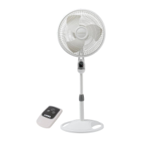
4. To secure Blade, screw Spinner onto Shaft
Counter Clockwise until tight on Blade hub.
Figure 8A
Pin
Groove
5. With fan head in upright position, align Ornament of Front Grill
so it is horizontal and right side up. By starting with the top of
the grill and working down, snap Grill in place. NO GRILL CLIPS
ARE NEEDED FOR ASSEMBLY.
No tome tubos separados. En caso de tuberías se separados,
insertar un tubo en el tubo B.
A
B
Thermostat
Button
Oscillation
Button
Power
Button
Timer
Button
Figure 9
NOTE: This fan circulates room air; it does not condition or
change the temperature of room air.
Manual mode operates the fan continuously. The fan starts in
manual mode when initially turned on.
8. After turning the Fan off, unplug the unit from the
electrical outlet.
IMPORTANT: Your LASKO pedestal fan is
equipped with a Climate Control Thermostat. This
Thermostat functions by sensing the tempera-
ture in the room and will turn the Fan on or off
AUTOMATICALLY as the temperature changes.
 Loading...