Do you have a question about the Laskomex CD-2502 Series and is the answer not in the manual?
Wiring system should be performed according to standard PN-IEC-60364-1 by an authorized person.
It is forbidden to connect the entry phone elements to installations other than made according to the recommendation.
No metal objects can be put into the openings in uniphones or monitors because this can cause electric shock or fire.
El. supply from external supply sources should not be connected to uniphone terminals because it can cause damage or fire.
It is forbidden to hold the receiver near an ear and push the lever (hook-switch) at the same time.
It is forbidden to repair the entry phone equipment by unauthorized persons because it may cause a threat to health and life.
El. supply from sources of parameters other than recommended by a producer should not be connected.
Get acquainted with the operation instructions especially with the entry phone conditions of use.
Define the final configuration, operation mode and then select the necessary elements.
Define the place of installation of the system elements.
Design the wiring system for the accepted configuration; select the kind and cross sections of wires.
Install the equipment of the entry phone system and connect according to the connection diagram.
Activate the system.
Set the operation parameters of the entry phone system. Inform occupants about use and hand out codes.
Check the operation of the system using the installation procedure.
The EC-2502 cassette is used for main or subordinate entrances and its operation mode is defined by the installer.
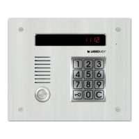
Various types of external panels are available in audio and video versions, made of coated sheet or stainless steel.
Vision signal distributors for video version, enabling connection of monitors and branching of installation.
Used for selecting video signal source from external panels, CVP-2 has additional inputs for more cameras.
The system can control electro-catch or electromagnetic lock; operation time is programmable.
Entry phone wiring depends on audio or video version. General recommendations for wiring system performance.
Electrical system according to PN-IEC 60364-1 by authorized person; wire cross-section depends on distance.
Adjust wave impedance to connected equipment. Resistors needed at beginning/end of line.
Set jumper JP1 in symmetrizator plate according to wire impedance. Set JP1 and JP2 in panel's electronic plate.
Steps for mounting the external panel under plaster, including drilling holes and fixing the panel.
Steps for mounting the panel casing on plaster, connecting wires, and fixing the panel.
Install electronic cassette and power supply adaptor inside the building, preferably in a place not accessible to unauthorized persons.
After installation, start procedure P-3 for installation and activation.
CD-2502 controls electro-catch or electromagnetic lock. Selection of control method via jumper ZT1.
For electromagnetic lock, set control frequency to 0. For electro-catch, remove jumper J3.
Floor distributors CVR-x installed in staircases with video entry phone. Fastened to wall by screws.
Connect wires to ARK terminals. RJ45 plugs for monitor wires. CVR-1 supplied from monitors.
CVR-2 requires 15V DC/4A external power supply adaptor for monitors.
To ensure clear picture, connect resistor at the end of line equal to wire impedance (100, 124, 136 Ω).
Assume uniphone connection wire is routed, connected to L+, L- terminals, and line is not shorted.
Program uniphone number by configuring jumpers inside uniphones. Max two uniphones per number.
Activation by one person. Start installation procedure P-3. Configure cassette, uniphones, and monitors.
Start programming mode, select procedure No. 3. Set upper/lower range of scanned numbers.
Start installation procedure (P-3-0). Exit programming mode (P-8).
Connect uniphone/monitor wires. Avoid short-circuits, especially for monitor supply.
Pick up uniphone receiver and press electro-catch pushbutton. Avoid holding receiver near ear.
After setup, hang up uniphone. System calls back. Check acoustic line and electro-catch.
9 procedures available for changing system operation parameters. Bring cassette to programming mode.
Touch key symbol five times, enter serial number or administrator key.
Parameter EtyP sets cassette for main (H) or subordinate (U) entrance. Changes may result in loss of data.
Parameters try (operation time) and FrY (frequency) control electro-catch and electromagnetic lock.
CEd permits occupants to edit codes. CPo blocks code editing. CE r disables wrong code signals.
Procedure P-3 checks uniphone functioning. Activation involves switching on, entering limit time.
P-4-0 (CO) resets all keys. Requires administrator code for protection.
P-4-4 deletes a key from memory after applying it to the reader. CAS message shown.
P-4-5 resets keys attributed to an apartment. Searches for first memory item and allows reset via C.
P-4-6 resets key in a defined memory item. CAS confirms deletion. FrEE if item is free.
Parameter 4 (Calling options) defines uniphone reaction: switched off, bell only, active uniphone.
Details on calling options: 'd' uniphone as bell, 'A' active uniphone, 'P' active uniphone without confirmation, 'b' active uniphone with camera off.
Parameter 5 (Entrance service) defines pushbutton operation of electro-catch at entrances.
Parameter 6 (Options of combination lock) defines if lock is on, and if occupants can change code/register keys.
Enables changing the installer's code for programming. Old code must be entered before new one.
Procedure to change coded lock code. Enter apartment number, then new 4-digit code twice.
This section covers the basic operations and usage of the entry phone system.
Enter apartment number. Uniphone rings, CALL message displayed. [OuO] indicates waiting for receiver pickup.
Conversation possible after receiver pickup. Electro-catch activated by button. Release signaled acoustically.
Do not press forks near ear. Activation of electro-catch does not break conversation. Key for gate drive.
Avoid loud signals by not pressing forks near ear. Electro-catch activation does not break conversation.
Enter apartment number and 4-digit code. Correct code releases electro-catch. Signals for correct/failed attempts.
Installer can block user's code change via P-5 parameters No. 4 and 6.
Place iButton or RFID key to reader. Phone reads serial number, compares with memory, opens electro-catch.
Access menu by pressing '9' four times. Shows system name and version. Allows changing parameters.
Steps to activate user menu: connect to apartment, press key, press catch button 5 times.
User can change coded lock code via user's menu. Option can be blocked by installer.
Restoring defaults loses recorded data (codes, keys, settings). Get acquainted with chapter content first.
Press INIT (SW2) and RESET (SW1) buttons to restore all default settings.
This section details wire selection and connection diagrams for various system configurations.
Figure 35 shows selection of wires for entry phone CD-2502 in audio version.
Figure 36 shows selection of wires for entry phone CD-2502 in video version.
Figure 43 shows CD-2502 video basic system for one staircase, including connections.
Figure 44 shows CD-2502 video multi-entrance system, including connections.
| Type | Corded |
|---|---|
| Caller ID | Yes |
| Call Waiting | Yes |
| Redial | Yes |
| Handset Volume Control | Yes |
| Display | LCD |
| Ringer Volume Control | Yes |