11
ECP5 PCI Express Board User’s Guide
Power Measurements (See Appendix B, "ECP5 Power" sheet)
The ECP5 PCI Express Board allows for easy power measurements with a multi-meter of the ECP5 device. The
ECP5 power rails are isolated and can be measured by measuring the voltage across power resistors.
Figure 9. ECP5 Power Measurements
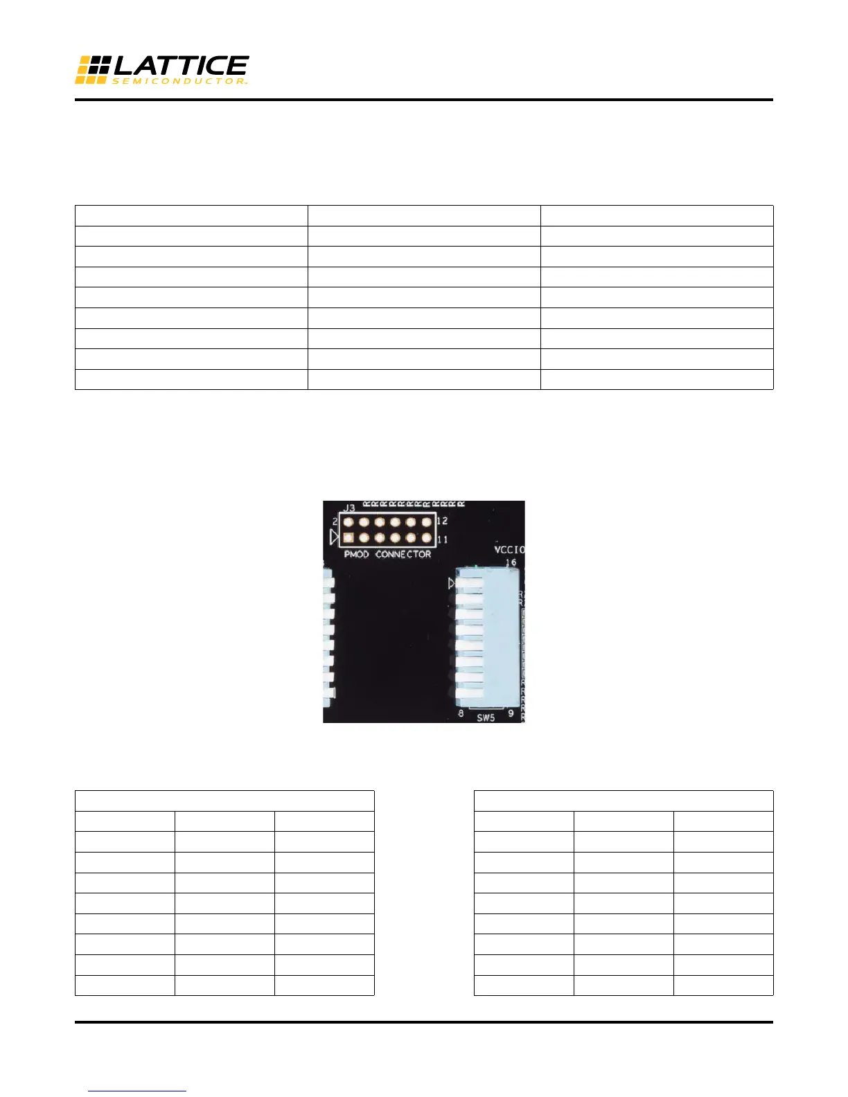
PMOD (See Appendix B, "ECP5 Config" sheet)
The ECP5 connects to a PMOD connector J3. To isolate the PVMOD connector from the FTDI device set all SW5
switches to 1 (Up=1).
Figure 10. PMOD Connector and Switches
Expansion Headers/Connectors (See Appendix B, "Card #1" and "Card #2" sheets)
Table 8. Expansion Connections
Voltage Rail Test Points Power Resistor Value (Ohms)
VCCAUX
TP19, TP18 0.1
VCC
TP13, TP12 0.01
VCCIO3_3 (Bank 8)
TP5, TP4 0.1
VCCIO2_5 (Bank 0, 1, 3, 4, 7)
TP16, TP17 0.1
VCCIO1_5 (Bank 2)
TP14, TP11 0.1
VCCIO1_2 (Bank 6)
TP36, TP37 0.1
VCCA
TP21, TP20 0.01
SERDES
TP22, TP24 0.1
CN1/J1 (Left) Expansion Connector CN2/J2 (Left) Expansion Connector
Pin Signal ECP5 Ball
Pin
Signal
ECP5 Ball
1
2.5 V
2.5 V 1
2.5 V
2.5 V
2
2.5 V
2.5 V 2
2.5 V
2.5 V
3
Lvcmos1_2
D16 3
Lvcmos2_2
C19
4
Lvcmos1_0
A16 4
Lvcmos2_0
F17
5
Lvcmos1_3
E16 5
Lvcmos2_3
E19
6
Lvcmos1C_1
B16 6
Lvcmos2C_1
E17
7
Lvcmos1_6
C15 7
Lvcmos2_6
A20
8
Lvcmos1_4
A15 8
Lvcmos2_4
D19