10
ECP5 PCI Express Board User’s Guide
Ethernet Interfaces (See Appendix B, "RJ45" sheet)
One Marvell 88E1512 Gigabit Ethernet transceiver device (U11) is included on the board. This physical layer
device supports 1000BASE-T, 100BASE-TX, and 10BASE-T applications via a standard media interface to a RJ45
connection. The RJ45 connection includes network magnetics providing the proper signal conditioning, electro-
magnetic interference suppression and signal isolation. This connector includes two LEDs and the board includes
four status LEDs from the Marvell device. The LEDs are register-programmed and detailed descriptions are avail-
able in the Marvell device data sheet.
Table 6. PHY Status Indicators
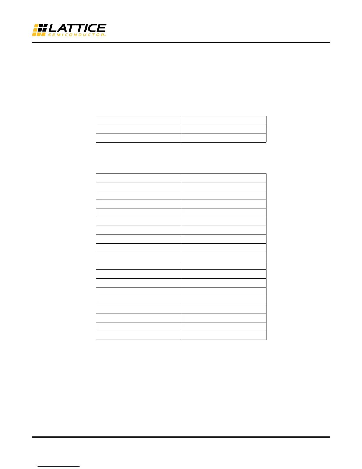
The Marvell 88E1512 device communicates via a RGMII interface to the ECP5 device.
Table 7. FPGA GPIO to RGMII Interfaces
LED Status Description
RJ45 (Yellow) LED RX
RJ45 (Yellow) LED TX
Signal PHY
RxClk A18
RxCtrl AC28
RxD0 A19
RxD1 F18
RxD2 D18
RxD3 B19
TxClk A2
TxCtrl AD29
TxD0 A5
TxD1 A4
TxD2 A3
TxD3 D7
Mdc AE30
Mdio AD30
CLK125 B29(URC_GPLL1T_IN)
CLK125 C17 (PCLKT0_0)
Resetn AC31
Config AE31