4
ECP5 PCI Express Board User’s Guide
your PC (with Diamond Programmer software installed). The USB hub on the PC will detect the addition of the USB
function, making the built-in cable available for use with the Diamond Programmer software.
Diamond Programmer Requirements
Note: This board includes the built-in download module and only requires the USB cable included with the board.
After initial board setup, use the following procedure to program the board. Instructions assume that Diamond Pro-
grammer software has been installed on a local PC.
Requirements:
• PC with Diamond Programmer 3.2 (or later) programming software, installed with appropriate drivers (USB driver
for USB cable).
Note: An option to install these drivers is included as part of the Diamond Programmer setup.
Board Programming
Configuration Status Indicators (See Appendix B, "XO2 Configuration Mux" sheet)
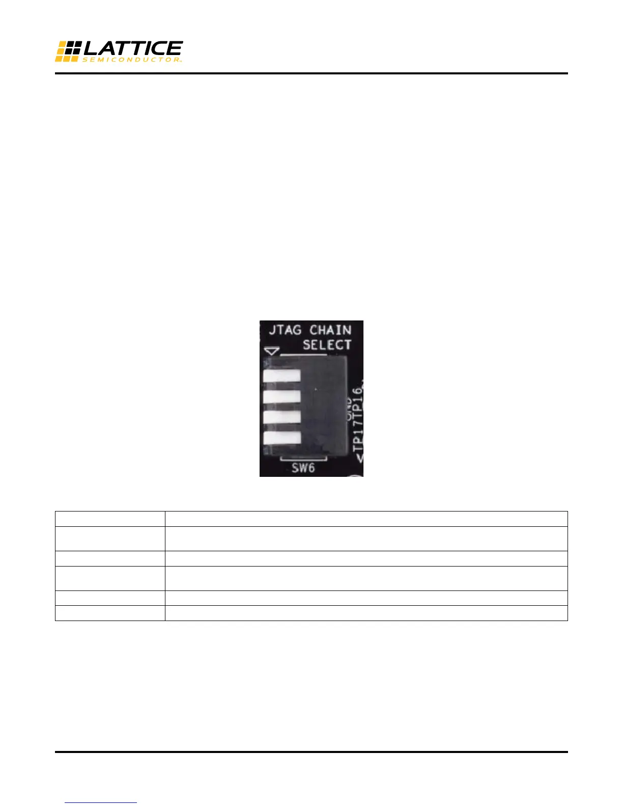
Figure 3. PCI Express Board Configuration/Programming Mux Selection
SW6 is used to select the device to program on the ECP5 PCI Express Board (1=Up, 0=Down).
SW7 includes the ECP5 CFG pins (1=Up, 0=Down) which allow the configuration mode of the ECP5 to be
selected. Switches are the right side of SW7 where SW7[1]=CFG0, SW7[2]=CFG1, SW7[3]=CFG2
SW6[1:4] Device Selected to Program or Configure
1111
MachXO2-640 (JTAG Mux). Note This device must be programmed before Programming or Config-
uring other devices. This device is pre-programmed during the boards manufacturing.
0000
ECP5UM-85
0001
ispClock-5304 (Clock Management) This device is controls the clock management on the board.
This device is pre-programmed during the boards manufacturing.
0010
Expansion Card on CN1 Connector (Left)
0100
Expansion Card on CN2 Connector (Right)