Quick Start Guide (EN)
X-431 PADII
LAUNCH
Pictures illustrated here are for reference purpose only and this Quick Start Guide is subject to change without notice.
Diagnostic Connector
1. Locate vehicle’s DLC socket: It provides standard 16 pins and is generally located on driver’s side, about 12 inch away
from the center of dashboard. See Figure DLC Location. If DLC is not equipped under dashboard, a label indicating
its position will be given. In case no DLC is found, please refer to Automobile Repair Manual;
2. Plug the connector into the vehicle's DLC(It is suggested to use the OBD II extension cable to connect the DLC and the
connector). For vehicles with non-16PIN DLC, please choose the desired connector. Normally the power indicator of
diagnostic connector will light up.
Note: Remember to remove the
diagnostic connector from the DLC
if it keeps unattended.
NEAR CENTER
OF DASH
DLC Location
1. Charge X-431 PADII Tablet
Except that power adaptor supplies power to X-431 PADII,
PADII can also obtain power from the Lithium polymer battery.
Choose any of the followings to charge X-431 PADII tablet:
1. Use the included 5V power adaptor: Connect one end of the
power adaptor to DC IN port of X-431 PADII, then connect the
other end to the AC outlet. We assume no responsibility for
damage or loss resulting from using other similar adaptors other
than the specified one.
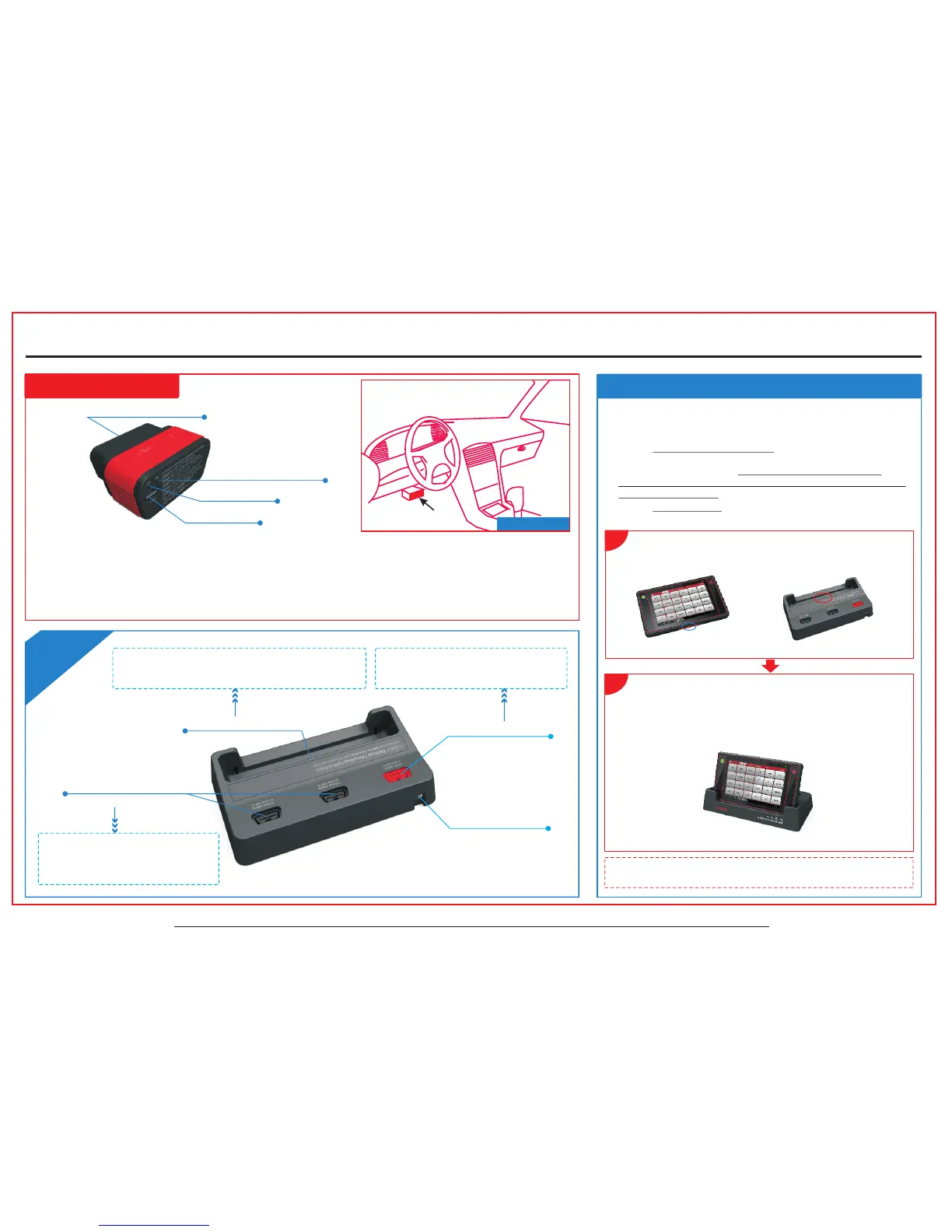
2. Use the docking station: Follow the steps described as below to
charge your X-431 PADII tablet:
X-431
Do
c
ki
ng
Sta
ti
o
n
Install diagnostic connector
Note: If X-431 PADII tablet keeps idle or unattended for a long
period, please lock the screen or turn it off to save power.
OBD II 16 PIN connector
Communication indicator
Power indicator
Micro USB port
Fig. a Fig. b
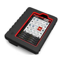
Locate the charging slot on the bottom of X-431 PADII tablet and
the docking station. See Fig. a & Fig. b.
1
*Note3: It is designed to charge the display tablet. For
details on how to charge, please refer to Section “Charge
X-431 PADII Tablet” on the right.
*Note5:
the socket for demo experience when the
station is connected to the AC outlet.
Plug the diagnostic connector into
Power Interface
3
Charging Slot
OBD 16 Socket without
4
power output
OBD 16 Socket with
5
power output
(Provides power to
the docking station)
*Note4: These 2 sockets are used to
store the additional DBScar/EasyDiag/
golo diagnostic connector (separately
purchased).
Fig. c
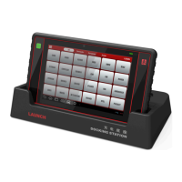
2
Align the charging slots, and then dock the tablet into the station
to ensure that it firmly sits on the docking station. Refer to Fig. c.
Insert one end of power cord of the docking station into the power
jack, then plug the other end into the AC outlet.
 Loading...