EasyManua.ls Logo

Lawler 802 - User Manual

Lawler 802
5 pages
Print Icon
To Next Page IconTo Next Page
Loading...
temperedwater.com
5330 East 25
th
St.
Indianapolis, IN 46218
Phone (317) 261-1212
Fax (317) 261-1208
INSTALLATION &
MAINTENANCE MANUAL
Design and specifications subject to change without notice.
Please refer to temperedwater.com to ensure most
current data sheet and other design solutions.
CAUTION: When maintaining and adjusting the
mixing valve, all xtures should be isolated from
use. Lawler Manufacturing Co., Inc. recommends
that you work safely at all times and in a manner
consistent with the OSHA Lock/Tagout standard,
29 CFR 1910.147 and other applicable standards.
temperedwater.com/patents
M 802 G
ASSE 1017 Approved
ASSE Lead Free Certied
Certied to CSA B125.3
NOTICE! No mixing valve will work satisfactorily if improperly installed. We suggest, therefore, that you read
these instructions carefully before installing and follow directions as outlined. Handle the mixing valve with care.
Model 802
Thermostatic Water
Controller
This installation & maintenance manual covers all
congurations of the 801 including manifold recirculation
systems, multiple valve systems and ARV systems.
CAPACITIES MODEL 802
Pressure Drop PSI 5 10 20 30 45 60 80
Valve Number Capacity
802-GPM 28 39 54 66 80 91 103
802-LPM 106 148 208 247 303 341 388
1/2 gpm when properly installed in recirculated system.
WARNING: This product contains chemicals known
to the State of California to cause cancer and birth
defects or other reproductive harm.
(Installer: California law requires that this warning
be given to the consumer.)
For more information: www.oehha.org/prop65
DIMENSIONS
Valve Number A N.P.T. B N.P.T. C D
802 1” 1-1/4” 11” 12”
Dimensions are for reference purposes only. For rough-in dimensions
please refer to Lawlers Revit/BIM models found at temperedwater.com.
73000_802_STD_DRW_NODIMS.pdf
B
A A
D
C
Question and Answer IconNeed help?

Do you have a question about the Lawler 802 and is the answer not in the manual?

Overview

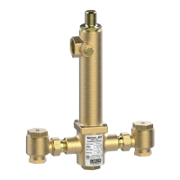
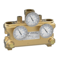
The Lawler Model 802 is a thermostatic water temperature controller designed to mix hot and cold water to a desired temperature within its operational range. It is suitable for both single and dual temperature recirculating systems.

Function Description

The Model 802 controller automatically mixes hot and cold water to maintain a consistent outlet temperature. It features built-in safety mechanisms to prevent scalding and ensure reliable operation. In the event of a cold water supply failure, the hot water ports reduce flow. Conversely, if the hot water supply fails, the cold water ports reduce flow. Should the thermostat itself fail, both ports reduce flow of hot and cold water, further enhancing safety. The controller is designed to be installed below the hot water tank or heater, or with a heat trap if installed otherwise.

Important Technical Specifications

  • Pressure Drop PSI (GPM):
    • 802-GPM: 28 PSI (39 GPM), 54 PSI (80 GPM), 91 PSI (103 GPM)
    • 802-LPM: 106 PSI (148 GPM), 208 PSI (247 GPM), 303 PSI (388 GPM)
    • (Note: GPM values are for 1/2 GPM when properly installed in recirculated system.)
  • Maximum Inlet Conditions:
    • Pressure: 125 psi
    • Temperature: 200°F
  • Factory Set Outlet Temperature: Normally 110°F, or as stamped on the label.
  • Hot Water Supply Requirement: Hot water supply should be at least 20°F higher than the maximum valve setting.
  • Connections: The valve features union end stop and check valves with removable strainers at each inlet.

Usage Features

  • Temperature Adjustment: The outlet temperature can be adjusted using a 5/32 allen key. To increase temperature, turn counterclockwise; to decrease, turn clockwise. A screw (#1) covers the adjusting screw (#2).
  • Recirculating Systems: The Model 802 is designed for use in recirculating systems. In a single temperature system, a tempered water return line allows flow through both ports during no-draw periods. For dual temperature systems, a separate recirculating loop and pump are required for high-temperature hot water return.
  • Aquastat Integration: An aquastat should be installed at the tempered water return pump to control pump operation based on return water temperature.
  • System Setup:
    1. Flush the system thoroughly after installation.
    2. Ensure hot water supply is at design temperature.
    3. Close and tag all fixtures.
    4. Turn off the recirculating pump.
    5. Create a draw greater than the minimum flow rating of the mixing valve.
    6. Allow water to flow until temperature is stable, then adjust if necessary.
    7. Start the recirculating pump and allow the system to reach set temperature.
    8. Adjust the aquastat to shut off the pump if return water exceeds the set point by 2°F and restart if it drops 5°F below the set temperature.
    9. Set the balancing valve to the full open position.
    10. Shut off all fixtures; the cold inlet to the mixing valve should be warm.
    11. Allow the system to run for at least 30 minutes in this no-draw condition.
    12. If water temperature increases during no-draw, slowly close the balancing valve until the temperature returns to the original set point.

Maintenance Features

  • Periodic Checks: The controller should be checked periodically.
  • Cleaning: The valve can be disassembled for cleaning. This involves removing the bonnet, thermostat, bottom plug, valve spring, and plunger. The liner and plunger should be cleaned and polished with fine emery cloth until the plunger moves freely.
  • O-Ring Replacement: O-rings (pusher O-ring #18, liner O-ring #10) can be replaced during cleaning.
  • Part Replacement: If the piston or liner is nicked or shows excessive wear, it should be replaced. Springs (valve spring #13, spring #13) can also be replaced if they lose strength.
  • Thermostat Testing:
    1. Place a 3/8" wooden dowel into the center of the thermostat and immerse in 85°F water. Mark a reference point on the dowel.
    2. Insert the thermostat into hot water at least 20°F higher than the set temperature.
    3. The dowel should move out approximately 1/8". If there's no movement or it can be pushed inward, a new thermostat is required.
  • Resetting the Mixing Valve: After repair or cleaning, the mixing valve may need to be reset. This involves turning off the recirculation pump, creating demand, inserting a 5/32 allen key into the set screw, turning it clockwise until it clicks, then turning it counterclockwise until the desired outlet temperature is reached.
  • Troubleshooting (Cold Water Shut-Off):
    • Turn on full hot and cold water, then shut off only the hot water stop and check valve. Cold water should flow momentarily then reduce to a negligible amount.
    • Failure indicates a sticking plunger or a weak spring (#13).
    • Lack of flow when cold (below 75°F) is normal; warming the thermostat with hot water should initiate flow if the thermostat is good.
  • Troubleshooting (Hot Water Shut-Off):
    • Allow full hot and cold water for one minute, then shut off only the cold water stop and check valve. Hot water should reduce to a negligible amount.
    • Failure indicates the hot water supply is not 20°F above the maximum temperature setting, or a sticking plunger.

Repair Kits and Assemblies:

Various repair kits are available, including a Complete Repair Kit, Piston & Liner Assembly, Stop & Check Repair Kit, Thermostat Repair Kit, Bonnet Assembly, and O-Ring & Gasket Kit. These kits contain specific parts for comprehensive maintenance and repair.

Lawler 802 Specifications

General IconGeneral
BrandLawler
Model802
CategoryControl Unit
LanguageEnglish

Related product manuals