EasyManua.ls Logo

Lawler 805 - User Manual

Lawler 805
5 pages
Print Icon
To Next Page IconTo Next Page
Loading...
temperedwater.com
5330 East 25
th
St.
Indianapolis, IN 46218
Phone (317) 261-1212
Fax (317) 261-1208
INSTALLATION &
MAINTENANCE MANUAL
Design and specifications subject to change without notice.
Please refer to temperedwater.com to ensure most
current data sheet and other design solutions.
CAUTION: When maintaining and adjusting the
mixing valve, all xtures should be isolated from
use. Lawler Manufacturing Co., Inc. recommends
that you work safely at all times and in a manner
consistent with the OSHA Lock/Tagout standard,
29 CFR 1910.147 and other applicable standards.
temperedwater.com/patents
M 805 F
ASSE 1017 Approved
ASSE Lead Free Certied
Certied to CSA B125.3
NOTICE! No mixing valve will work satisfactorily if improperly installed. We suggest, therefore, that you read
these instructions carefully before installing and follow directions as outlined. Handle the mixing valve with care.
Model 805
Thermostatic Water
Controller
This installation & maintenance manual covers all
congurations of the 801 including manifold recirculation
systems, multiple valve systems and ARV systems.
CAPACITIES MODEL 805
Pressure Drop PSI 5 10 20 30 45 60 80
Valve Number Capacity
805-GPM 64 96 133 165 200 230 265
805-LPM 242 363 503 624 757 870 1003
1/2 gpm when properly installed in recirculated system.
WARNING: This product contains chemicals known
to the State of California to cause cancer and birth
defects or other reproductive harm.
(Installer: California law requires that this warning
be given to the consumer.)
For more information: www.oehha.org/prop65
DIMENSIONS
Valve Number A N.P.T. B N.P.T. C D
805 2” 2” 15” 13-1/2”
Dimensions are for reference purposes only. For rough-in dimensions
please refer to Lawlers Revit/BIM models found at temperedwater.com.
73100_805_STD_DRW_NODIMS.pdf
B
A A
D
C
Question and Answer IconNeed help?

Do you have a question about the Lawler 805 and is the answer not in the manual?

Summary

Model 805 Overview and Specifications

Model 805 Controller Description

Introduces the Model 805 Thermostatic Water Controller.

Model 805 Flow Rate Capacities

Details the flow rate capacities based on pressure drop.

Model 805 Physical Dimensions

Provides key physical dimensions for installation planning.

Performance and Safety Features

Product Performance Safety Features

Explains safety features like reduced flow on supply failure.

Maximum Inlet Conditions

Specifies the maximum allowable pressure and temperature for inlet water.

Maintenance and Adjustment Procedures

Routine Maintenance Checks

Describes periodic checking and cleaning procedures for the controller.

Cold Water Shut-Off Test

Procedure to verify proper cold water shut-off function.

Hot Water Shut-Off Test

Procedure to verify proper hot water shut-off function.

Valve Inspection and Cleaning

Detailed steps for inspecting and cleaning internal valve components.

Mixing Valve Reset Procedure

Steps to reset the mixing valve after repair or cleaning.

Outlet Temperature Adjustment

Guide on how to adjust the outlet water temperature setting.

Thermostat Testing Procedure

Thermostat Testing Steps

Instructions on how to test the thermostat's functionality in water.

Repair Parts and Kits

Model 805 Repair Parts List

Lists individual repair parts with their part numbers.

Repair Kits and Assemblies

Details available repair kits and the parts they contain.

Installation and System Setup

Typical Installation Guidelines

Recommendations for installing the mixing valve below the water heater.

Setting the Mixing Valve to the System

Step-by-step guide for setting the mixing valve within a recirculating system.

Overview

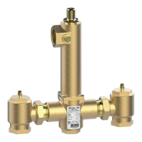
The Lawler Model 805 Thermostatic Water Controller is a device designed to mix hot and cold water to achieve and maintain a desired outlet temperature. It is suitable for various applications, including single and dual temperature recirculating systems.

Function Description

The primary function of the Model 805 is to provide precise thermostatic control over water temperature. It blends hot and cold water to deliver a consistent temperature within a specified range. The valve incorporates several safety features:

  • Cold Water Supply Failure: If the cold water supply fails, the hot water ports automatically reduce hot water flow, preventing scalding.
  • Hot Water Supply Failure: If the hot water supply fails, the cold water ports reduce cold water flow.
  • Thermostat Failure: In the event of thermostat failure, both hot and cold water ports reduce flow, ensuring a safe condition.

The controller is equipped with union end stop and check valves at each inlet. These valves prevent water from bypassing between the hot and cold water supply lines and should be fully open during operation. The device is designed to deliver 1/2 GPM when properly installed in a recirculated system.

Important Technical Specifications

  • Capacities (GPM/LPM) at various Pressure Drops (PSI):
    • 5 PSI: 64 GPM (242 LPM)
    • 10 PSI: 96 GPM (363 LPM)
    • 20 PSI: 133 GPM (503 LPM)
    • 30 PSI: 165 GPM (624 LPM)
    • 45 PSI: 200 GPM (757 LPM)
    • 60 PSI: 230 GPM (870 LPM)
    • 80 PSI: 265 GPM (1003 LPM)
  • Maximum Inlet Conditions:
    • Pressure: 125 PSI
    • Temperature: 200°F
  • Valve Number: 805
  • N.P.T. (Nominal Pipe Thread) Sizes:
    • A: 2"
    • B: 2"
  • Dimensions:
    • C: 15"
    • D: 13-1/2"
  • Certifications: ASSE 1017 Approved, ASSE Lead Free Certified, Certified to CSA B125.3.

Usage Features

The Model 805 is designed for ease of installation and integration into various plumbing systems.

  • Installation: It is recommended to install the mixing valve below the hot water tank or heater. If this is not possible, a heat trap with an approximate 2' drop should be piped in. For recirculating systems, a tempered water return line should be connected to allow flow through both ports of the mixing valve during periods of no draw. In dual temperature systems, a separate recirculating loop and pump are required for high-temperature hot water. An aquastat should be installed at the tempered water return pump.
  • Temperature Adjustment: Valves are factory set for a maximum 110°F outlet temperature. To adjust the temperature, remove screw #1, then use a 5/32" allen key to turn adjusting screw #2 counterclockwise to increase temperature or clockwise to decrease it. Replace screw #1 once the desired temperature is set. If a desired outlet temperature is 15°F or more higher than the stamped label, a special thermostat may be required.
  • System Setup: After installation, the system should be thoroughly flushed. Ensure the hot water supply is at the normal design temperature. All fixtures must be closed and tagged to prevent use during setup. The recirculating pump should be turned off, and a draw greater than the minimum flow rating of the mixing valve should be created. Once the water temperature is stable, the mixing valve can be readjusted. After setting the temperature, the recirculating pump is started, and the system is allowed to reach the set temperature. The aquastat at the return pump should be adjusted to shut off the pump if the return water exceeds the set point by 2°F and restart when it drops 5°F below the set temperature. The balancing valve should be set to the full open position. After shutting off all fixtures and ensuring no draw, the system should run for at least 30 minutes. If water temperature increases during a no-draw period, the balancing valve should be slowly closed until the water temperature returns to the original set temperature.

Maintenance Features

Regular maintenance is crucial for optimal performance and longevity of the Model 805.

  • Periodic Checks: The controller should be checked periodically for proper setting and operation. This involves verifying the outlet temperature against the label and performing cold and hot water shut-off tests.
  • Cold Water Shut-Off Test: Turn on full hot and cold water, then shut off only the hot water stop and check valve. Cold water should flow momentarily and then reduce to a negligible amount. Failure indicates a sticking plunger or a weak spring.
  • Hot Water Shut-Off Test: Allow full hot and cold water to flow for one minute, then shut off only the cold water stop and check valve. Hot water should reduce to a negligible amount. Failure indicates an insufficient hot water supply temperature or a sticking plunger.
  • Inspection and Cleaning:
    1. Shut off hot and cold water supplies.
    2. Remove bonnet #19 to replace pusher O-ring #18.
    3. Remove thermostat #22 and clean it.
    4. Unscrew bottom plug #14 and remove valve spring #13 and plunger #12. If the assembly doesn't slide out, remove the plunger with liner #11 and gently tap until it frees.
    5. Clean and polish the liner and plunger with fine emery cloth until the plunger moves freely.
    6. Replace liner O-ring #10 if the liner is out.
    7. Replace piston or liner if nicked or shows excessive wear.
    • Caution: The liner and plunger are delicate and must be handled carefully. The liner must be inserted correctly, with the smaller diameter end going in first through the bottom plug opening.
  • Resetting the Mixing Valve: After repair or cleaning, a "reset" may be needed. Turn off the recirculation pump, create demand on the valve, and insert a 5/32" allen key into the set screw. Turn the set screw clockwise until a click is felt, then turn it counterclockwise until the desired outlet temperature is reached.
  • Thermostat Testing: Place a 3/8" wooden dowel rod into the center of the thermostat and place it in 85°F water. Mark a reference point on the rod. Then, insert the thermostat into hot water at least 20°F higher than the set temperature. The rod should move out approximately 1/8". If there is no movement or it can be pushed inward, a new thermostat is required.
  • Repair Kits and Assemblies: Various repair kits are available, including a complete repair kit, piston & liner assembly, stop & check repair kit, thermostat repair kit, bonnet assembly, and O-ring & gasket kit. These kits contain specific parts for comprehensive maintenance.

The manufacturer guarantees the Lawler Mixing Valve to be free from defects in workmanship and material for one year from the date of purchase.

Lawler 805 Specifications

General IconGeneral
BrandLawler
Model805
CategoryController
LanguageEnglish