D
V1
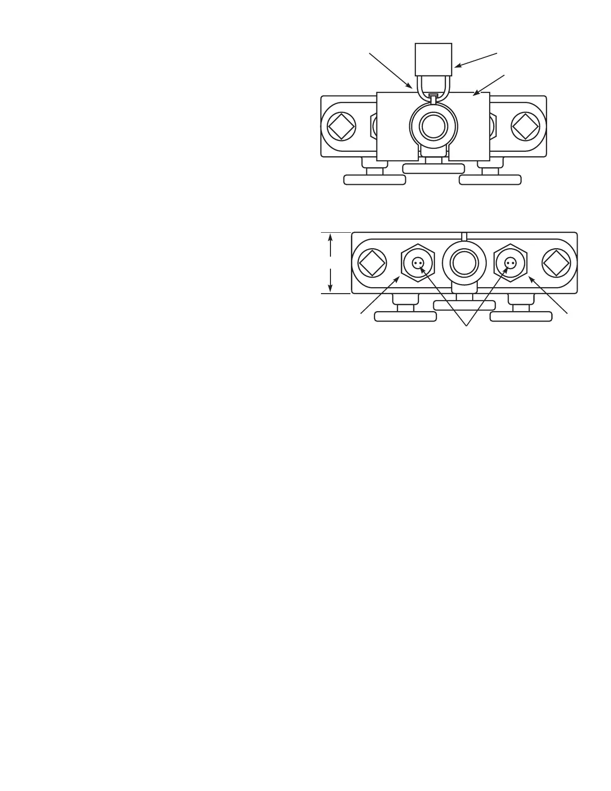
#3 CAP SCREWS
SAFETY LATCH #1 PADLOCK (optional)
#2 LOCKOUT PLATE
Setting the Mixing Valve
Prior to adjusting the temperature on the emergency mixing
valve be aware that prior to shipping this valve was tested
and set at the factory. Please make sure that isolation
valves and check valves are installed and that incoming
hot and cold pressures are equal before any adjustment
is made. If these parameters are not present, DO NOT
proceed to “Setting the Mixing Valve” until these parameters
are met. IT IS ADVISED TO CALL THE FACTORY PRIOR
TO DOING ANY TEMPERATURE ADJUSTMENTS ON ANY
LAWLER EMERGENCY THERMOSTATIC MIXING VALVE.
This mixing valve has been set at the factory to deliver
85°F outlet ow. Should the valve require adjustment, or an
application require a different set temperature, proceed as
follows:
1. Contact the proper medical and safety authorities to
determine correct water temperature for the specic
application.
2. If the valve is outtted with a padlock #1 and lockout
plate #2, unlock and remove.
3. Use a spanner wrench to remove the tamper-resistant
cap screws #3.
4. Create a draw on the mixing valve by opening a
downstream shower xture.
5. Insert a 5/32” allen key into the cap opening of valve 1
(V1) and seat in the adjustment screw (not shown). Set
the outlet temperature by turning the adjustment screw
clockwise to reduce temperature, counterclockwise
to increase temperature. Use thermometer (T1) to
measure the outlet temperature.
6. Adjust valve 2 (V2) using the same procedure used to
adjust valve 1 (V1).
7. Examine thermometers T1 and T2. Valve 1 and valve
2 should be set to the same temperature and the outlet
temperature should be 85°F or as specied for your
application. Adjust if necessary.
8. Replace cap screws #3, lockout plate #2 and padlock
#1.
 Loading...