Do you have a question about the LAWO mc236 MKII and is the answer not in the manual?
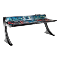
Describes the mc236 MKII control surface, its integrated local IO, dual redundant power supplies, and internally mounted A_UHD Core.
Details the two standard frame sizes: 16-fader and 32-fader, including dimensions and weights for Studio and OB-Van versions.
Explains the differences between Studio (table-top) and OB-Van (crossbar) mounting, including side panel options and part numbers.
Details the centre section components: Channel Display, Blanking Panel, Central Panel with faders, rotary encoders, and displays.
Describes the additional channel bay panels for the 32-fader variant: Channel Display and Fader Panel with faders, encoders, and displays.
Explains the overbridge, which features a full height blanking panel for mounting external devices like a tablet.
Identifies and describes the connectors and features on the rear panel, including script tray, ventilation, mains, grounding, and I/O panels.
Illustrates the internal wiring of the control surface, detailing connections between bays, servers, and the A_UHD Core via Ethernet.
Instructions on how to unpack the console and check contents. Advises contacting Lawo for transport damage.
Lists the items included with the console and optional items that must be ordered separately.
Details mounting for Studio (table-top) and OB-Van (crossbar) versions, emphasizing horizontal fader orientation and airflow.
States that dimensions and weight vary by frame variant and control panel options, directing users to data sheets.
Specifies operating temperature and humidity ranges, and highlights the importance of minimum distances for proper cooling.
Provides diagrams and specifies minimum air outlet and inlet clearances for Studio and OB-Van frame mounting.
Guides on connecting the USB keyboard to the correct port and selecting the keyboard layout in system settings.
Instructions for attaching and using the optional script tray, including weight limits and removal for transportation.
Details the various rear panel connections for power, grounding, audio (IO), synchronization, and management networks.
Explains dual-redundant power supplies, PSU block location, electrical specifications, and mains connection requirements.
Details how to establish an additional ground for EMC reasons using the CASE grounding screw and ensuring system potential.
Describes connecting to the mc² control system via MGMT A/B ports, emphasizing network switch use and cable specifications.
Details the built-in Local IO features, connectors (XLR, MADI, GPIO), and internal wiring to the A_UHD Core.
Explains using Media Network IO ports for audio-over-IP streaming (RAVENNA, AES67, ST2110) and the importance of network configuration.
Lists available optional I/O connection kits for Media Network ports, detailing SFP modules, cables, and connectors.
Step-by-step guide for installing I/O connection kits, including preparation, component assembly, and physical installation of cables and connectors.
Describes connecting external sync references using CLOCK IN/OUT (Wordclock) BNC connectors and ensuring matching frequencies.
Lists connections on the front buffer: ETH A network port, USB ports for control system and A_UHD Core, and stereo headphone output.
Details connecting a talkback microphone via the female XLR on the Central Panel, and its wiring to the rear TB connector.
Emphasizes reading safety instructions, handling sensitive components with care, ensuring ESD-proof workspace, and performing electrical safety checks.
Procedure for restarting bay servers via a recessed button, used for resolving display freezes or unresponsive controls.
Step-by-step guide for removing and replacing Fader or Central Panels, including screw removal, panel lifting, and connector disconnection.
Instructions on how to use the Hood Fastener to keep panels securely in place while working inside the console frame.
Detailed procedure for replacing a single fader unit, involving panel removal, cover plate detachment, cable disconnection, and fader unit replacement.
Guide for replacing touch-screen displays, including screw removal, connector disconnection, careful removal, and reinstallation.
Explains the function of DIP switches and rotary switches on Bayservers/Gateservers for configuration, including GUI mode and bay addressing.
Instructions for accessing and adjusting Bayserver DIP and rotary switches, noting that Gateserver settings are similar.
Procedure for replacing the dual-redundant PSU block, involving disconnecting mains, removing panels, and detaching connectors and screws.
Steps to replace the self-contained Local IO unit, including disconnecting cabling, removing panels, and sliding the unit out.
Guide for replacing the internal network switch, involving removal of panels, disconnection of connectors, and securing the new unit.
Procedure for replacing the A_UHD Core, emphasizing backup of user data, panel lifting, connector disconnection, and unit replacement.
Lists part numbers for system components, frame variants, mounting options, internal components, and accessories.
Provides links to PDF diagrams showing the mechanics of different control surface variants.
Provides links to PDF diagrams detailing the control surface's internal wiring, including control and power connections.
Details pin-outs and specifications for various connectors including Mic/Line In, Talkback, Line Out, AES3, and MADI.
Explains the SMPTE ST2022-7 (Seamless Protection Switching) method for recovering lost data packets in IP networks.
| Brand | LAWO |
|---|---|
| Model | mc236 MKII |
| Category | DJ Equipment |
| Language | English |