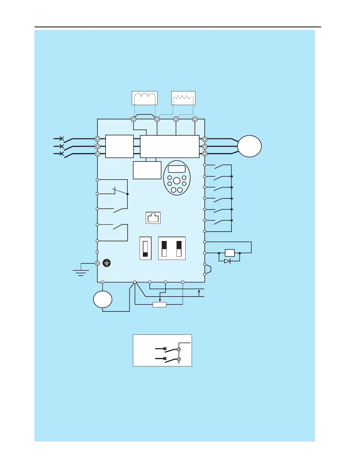
MCCB
*1
R/L1
S/L2
T/L3
U/T1
V/T2
W/T3
I M
FC
FB
FA
RY
PCS
RC
Motor
FR
RR
RST
DFL
DFM
DFH
COM
P24V
DRV
OM
COM
FRQ
PCS
COM
VRF
VRF2
+V
+
+
−
−
P1
P(+)
PR N(-)
Voltage signal: 0-10V
(Current signal: 4-20mA)
External potentiometer (1-10kΩ)
(or input voltage signal across VRF2-COM terminals: 0-10V)
Control
circuit
Operation
panel
Fault detection relay
Ry
HF-320α
Frequency
meter
(ammeter)
Main circuit
Noise
filter
DC reactor (DCL)
*2 (option)
Connector for
common serial
communications
Foward
Reverse
Reset
Preset-speed 1
Preset-speed 2
Preset-speed 3
Common
Braking resistor (option)
MCCB (2P)
R/L1
S/L2
Power supply
1φ200~240V
-50/60HZ
Speed reach
signal output
I ISINK
SW1
SOURCE
FRQ
V
VRF
V
Main circuit power supply
200V class: 3-phase
200-240V -50/60Hz
400V class: 3-phase
380-500V -50/60Hz
*3
Low-speed
signal output
*1: The T/L3 terminal not providedfor signal-
phase models.
Use the R/L1 and S/L2 terminal as input
terminals.
*2: The inverter came with the P1 and the P(+)
terminals shorted by means of a shoeting
bar.
Before installing the DC reactor (DCL),
remove the bar.
*3: When using the DRV output terminal in sink
logic mode, short-circuit the OM and COM
terminals.
 Loading...