4
Before Using Our Inverters
■
Selecting the Capacity (Model) of the Inverter
Selection
● Capacity
Refer to the applicable motor capacities listed in the standard
specifications.
When driving a high-pole motor, special motor, or multiple
motors in parallel, select such an inverter that the sum of the
motor rated current multiplied by 1.05 to 1.1 is less than the
inverter's rated output current value.
● Acceleration/Deceleration Times
The actual acceleration and deceleration times of a motor
driven by an inverter are determined by the torque and
moment of inertia 2 of the load, and can be calculated by the
following equations.
The acceleration and deceleration times of an inverter can be
set individually. In any case, however, they should be set
longer than their respective values determined by the
following equations.
Acceleration time
ta =
(J
M
+J
L
) u'N
(sec)
9.56 u (T
M
+ T
L
)
Deceleration time
ta =
(J
M
+J
L
) u'N
(sec)
9.56 u (T
B
+ T
L
)
J
M
: Moment of inertia of motor (kg·m
2
)
J
L
:
Moment of inertia of load (kg
·
m
2
)
(converted
into value on motor shaft)
'N: Difference in rotating speed between before
and after acceleration or deceleration (min
-1
)
Conditions T
L
: Load torque (N·m)
T
M
:
Motor rated torque x 1.2-1.3 (N
·
m) [V/f control]
Motor rated torque x 1.5 (N·m) [Vector
operation control]
T
B
: Motor rated torque x 0.2 (N·m)
When a braking resistor or a braking resistor
unit is used:
Motor rated torque x 0.8-1.0 (N·m)
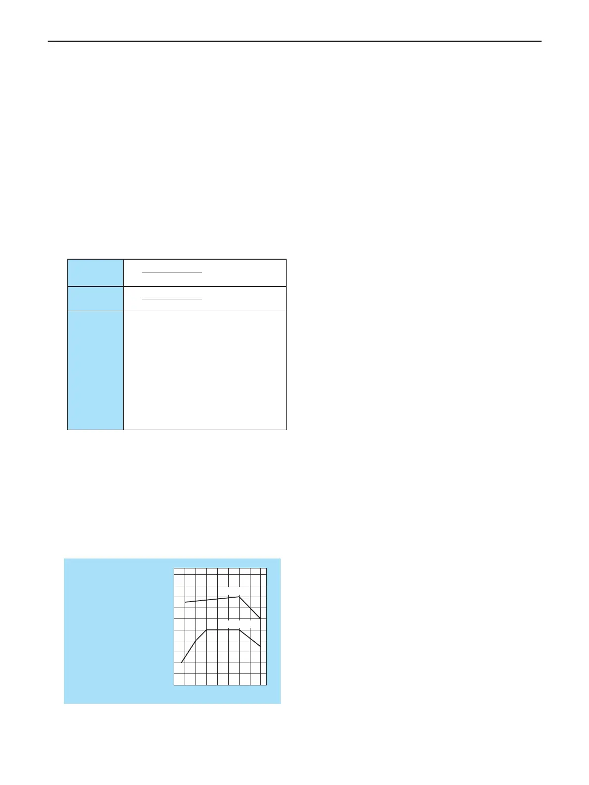
● Allowable Torque Characteristics
When a standard motor is combined with an inverter to
perform variable speed operation, the motor temperature
rises slightly higher than it normally does during commercial
power supply operation. This is because the inverter output
voltage has a sinusoidal (approximate) PWM waveform. In
addition, the cooling becomes less effective at low speed, so
the torque must be reduced according to the frequency.
When constant-torque operation must be performed at low speeds,
use an AF motor designed specifically for use with inverters.
Note 1. 100% of torque refers to the amount of torque that the motor
produces when it is running at a 60Hz-synchronized speed. The
starting torque is smaller in this case than that required when power
is supplied from a commercial power line. So, the characteristics of
the machine to be operated need to be taken into consideration.
Note 2. The maximum allowable torque at 50Hz can be calculated
approximately by multiplying the maximum allowable torque at a
base frequency of 60Hz by 0.8.
● Starting Characteristics
When a motor is driven by an inverter, its operation is
restricted by the inverter’s overload current rating, so the
starting characteristic is different from those obtained from
commercial power supply operation.
Although the starting torque is smaller with an inverter than
with the commercial power supply, a high starting torque can
be produced at low speeds by adjusting the V/f pattern torque
boost amount or by employing vector control. (200% in
sensorless control mode, though this rate varies with the
motor characteristics). When a larger starting torque is
necessary, select an inverter with a larger capacity and
examine the possibility of increasing the motor capacity.
■ Harmonic Current and Influence to
Power Supply
● Harmonics are defined as sinusoidal waves that is multiple
freguency of commercial power (base frequency: 50Hz or
60Hz). Commercial power including harmonics has a
distorted waveform.
Some electrical and electronic devices produce distorted
waves in their rectifying and smoothing circuits on the input
side. Harmonics produced by a device influence other
electrical equipment and facilities in some cases (for example,
overheating of phase advancing capacitors and reactors).
■ Measures for Suppressing Higher
Harmonics when Driving with Inverter
● Connecting a Reactor
Harmonic current leakage from the inverter may be suppressed
by connecting an input AC reactor (ACL) to the input side of
the inverter or DC reactor (DCL) to the DC section of the
inverter.
1. Input AC Reactor (ACL)
Used to improve the input power factor, reduce the harmonics,
and suppress external surge on the inverter power source
side.
2. DC Reactor (DCL)
DC reactor is more efficient on improving power factor for
inverter power source side. Use input AC reactor together,
for suppressing external surges.
Note: Refer to section on Peripheral Equipments, or Options for
measures on high frequency noise when using inverters.
 Loading...