740100-00(5) Page 3 of 14
ELECTRICAL SPECIFICATIONS
AC input voltage .....................................................120 VAC
AC fuse ..................................................................120 VAC, 2.5 A time-delay fuse
Motor protection .....................................................Solid state failure detection and shutdown
Activate inputs ....................................................... dry NO contacts (close contacts to open door)
Safety inputs ..........................................................dry NO contacts (closed contacts indicate an obstruction)
Breakaway input ....................................................dry NC contacts (open contacts indicate breakaway)
3-position switch input............................................dry 3-position switch
Power Boost disable input......................................dry NO contacts (close contacts to disable Power Boost
Lock output ............................................................Form C dry relay contacts rated 8 A, 30 VDC maximum
Accessory power output.........................................24 VAC, 1.5 A (protected by resettable thermal fuse)
Logic power output .................................................5 V, 50 mA (protected by resettable thermal fuse)
1. PRE-INSTALLATION SITE AND PRODUCT CHECK
1.1. All required installation steps listed before “8. Control Box Installation” in the Astro/Middle/Senior
Swing installation instructions (part No. 740132-00) should be completed before installing the
Middle/Senior Swing control box.
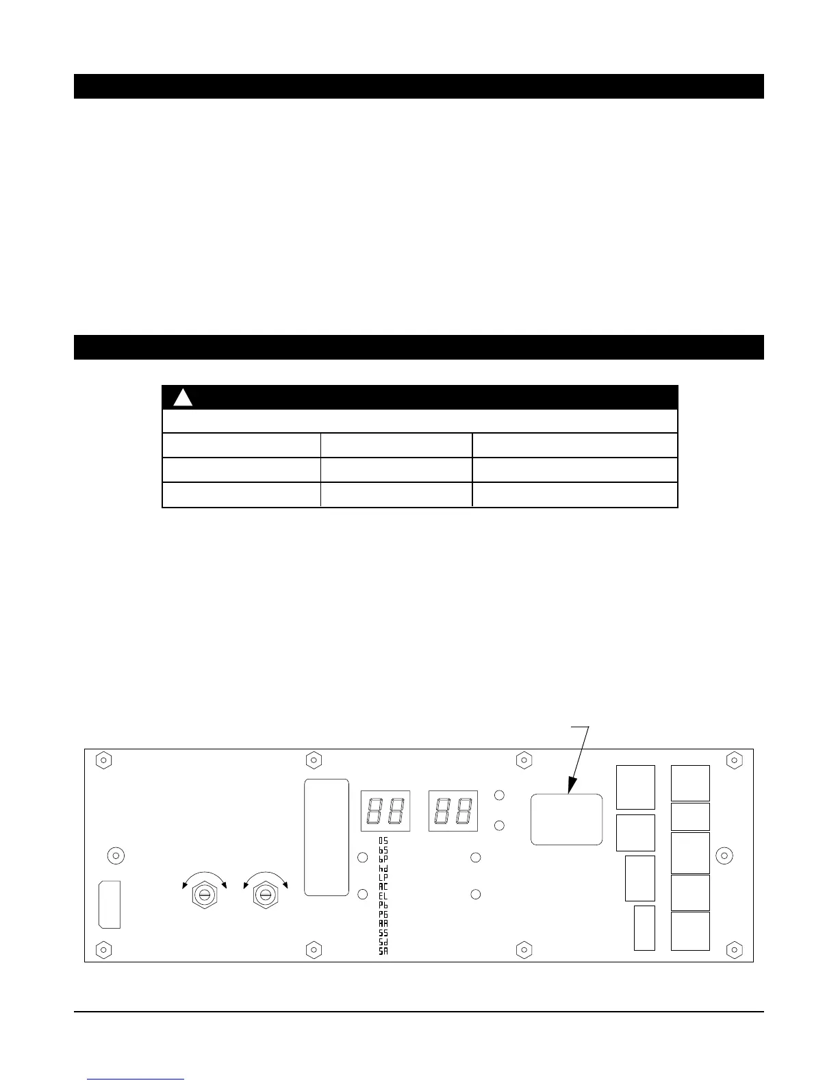
1.2. Check that the control box model (indicated on control box label; Figure 1-1) is correct for the application.
1.3. Check that the available AC voltage matches the control box voltage requirement (120 VAC).
1.4. Check that all accessories required for the application are on hand.
IMPORTANT
!
Type Width per Leaf Maximum Weight per Leaf
Single Door 36” to 48” 200 lb.
Simultaneous Pair 30” to 48” 200 lb.
Factory Authorized Door Leaf Size and Weight
Figure 1-1
Label indicates model
CAUTION: 120 VAC
2.5 A TIME-DELAY FUSE
WARNING: FOR CONTINUED
PROTECTION AGAINST FIRE,
REPLACE ONLY WITH SAME
TYPE AND RATING OF FUSE.
COMPANION
MOTOR
COMPANION MASTER
CLOSE
SPEED
S
L
O
W
F
A
S
T
CLOSE
SPEED
S
L
O
W
F
A
S
T
: OPENING SPEED
: BACKCHECK SPEED
: BACKCHECK POS.
: HOLD-OPEN DELAY
: LATCH POSITION
: AUTO-REV. CLOSING
: ELECTRIC LOCK
: POWER BOOST
: PUSH ‘N’ GO
: ALTERNATE ACTION
: SAFETY SLOW/STOP
: SLOWDOWN DISABLE
: RESERVED
SETTING
VALUE
DEFAULT
POWER
ON
UP
DOWN
UP
DOWN
WARNING: ALL SPEED
SETTINGS (OPENING,
CLOSING, AND LATCHING)
AND HOLD-OPEN TIME-
DELAY MUST BE FIELD
ADJUSTED TO MEET
LATEST APPLICABLE ANSI/
BHMA STANDARDS.
DMSS
#2
APPROACH
P5
DMSS
#2
SAFETY
P4
ELECTRIC
LOCK
P10
RETROFIT
P8
BODYGUARD
P1
ACTIVATE
P6
ACTIVATE
P7
DMSS
#1
APPROACH
P3
DMSS
#1
SAFETY
P2
LCN
®
XXXX SWING
XXXX-00
SN: XXXX
No Serviceable
Parts Inside
 Loading...