DMX Addressing Example
The following is a scenario on how to properly address and use the LSG/DMX
Interface.
Two fans are required ( Fan1, Fan2) to start and stop using a DMX signal. These
two fans have a combined Amperage load of less than 12 Amps.
The DMX address of the first fan is channel #440.
1.) Plug Fan 1 power into Auxilliary Output #1, and plug Fan 2 power into
Auxilliary Output #2.
2.) Plug main power of the LSG/DMX Interface into a 115 VAC source with a
minimum load rating of 12 Amps.
3.) Turn on Main power switch of the LSG/DMX Interface as well as the main
power to the 2 fans.
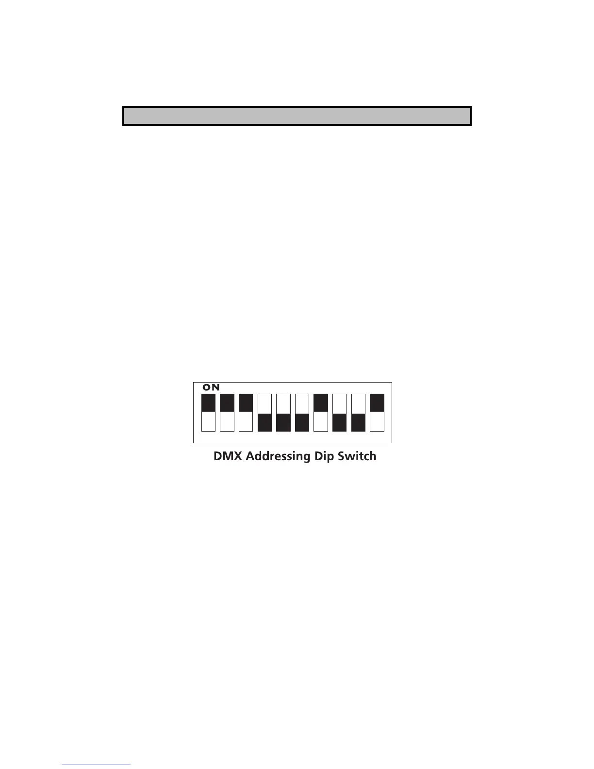
4.) To address the proper DMX channel on the DMX Addressing Dipswitch, we
must refer to the Binary Addressing Table located further in the manual.
The address table notes that channel # 440 is entered into the dipswitch as
follows: 000111011. the DMX Addressing Dip Switch should look like this:
5.) When channel #440 is activated at the DMX control source, Fan 1 will turn
on. By default, when Channel 441 is activated ( 440+1=441) at the DMX control
source, Fan 2 will turn on.
3