Do you have a question about the Leader LAG-55 and is the answer not in the manual?
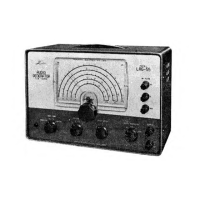
The LEADER Model LAG-55 Audio Generator is a dependable high quality instrument for measurements from 20 to 200,000 cps.
Highlights capabilities like sine, square, and complex waveforms, stable operation, and rugged construction.
Specifies frequency range, accuracy, stability, output impedance, and waveform output details.
Details distortion levels, square wave response, complex wave characteristics, and high pass filter frequency.
Lists tube complement, power supply requirements, size, and weight of the instrument.
Lists the main functional circuits comprising the audio generator.
Explains the function of each control on the front panel of the LAG-55.
Provides recommendations for line voltage, cabling, and warm-up for optimal performance.
Outlines the setup and procedure for measuring amplifier frequency response.
Details how to use square waves for testing amplifier characteristics and diagnosing faults.
Explains the oscilloscopic method for performing intermodulation distortion measurements.
Provides tables for converting voltage ratios to decibels for gain and loss.
Conversion table relating power in watts to voltage and power ratio in dB.
Table listing voltage multiplier 'K' for different load resistors.