EasyManua.ls Logo

Leading Edge GA-CTRL-008A - User Manual

Leading Edge GA-CTRL-008A
2 pages
Print Icon
To Next Page IconTo Next Page
Loading...
Tel: +44 (0)845 652 0396 Skyrrid Farm, Pontrilas, Hereford. HR2 0BW. UK www.leturbines.com
3-Pole Run/Stop Switch (GA-CTRL-008A)
Only operate in light winds
Introduction
Please read this manual thoroughly before attempting to assemble, install or operate your run/stop
switch. This will assure optimum performance and safety.
The run/stop switch is designed to allow the user to dynamically brake the LE-600 wind turbine at
will. This is achieved by disconnecting the power output of the turbine from the relevant load and
diverting it to a short circuit which then applies the dynamic braking effect on the permanent
magnet alternator of the turbine. This will bring the turbine to a near stop for maintenance only.
The run/stop switch can be used with turbines of different manufacture as long as the relevant
turbine has the following characteristics:
3-phase Wild AC not exceeding 150 V & 20 A
Mechanically and electrically capable of dynamic braking
Operation & Specification
The run/stop switch should be operated during low speeds as repeated use at high speeds may
cause damage if the turbine head (it was not designed to withstand repeated dynamic braking
operations).
The switch has two positions:
Position 1: Turbine 'Stop' position. The turbine is dynamically braked and may rotate very slowly.
Position 2: Turbine 'Run' position. The turbine output is allowed to flow straight through the switch.
Question and Answer IconNeed help?

Do you have a question about the Leading Edge GA-CTRL-008A and is the answer not in the manual?

Summary

Introduction to Run;Stop Switch Operation

Run;Stop Switch Operation and Specifications

Turbine Stop Position

Turbine is dynamically braked and may rotate very slowly.

Turbine Run Position

Turbine output is allowed to flow straight through the switch.

Safety Precautions

Mechanical Safety Hazards

Ensure turbine is restrained during installation to prevent operation.

Electrical Safety Hazards

Risks from rectified DC voltage, cable sizing, fuses, and battery short circuits.

Installation Guide

Overview

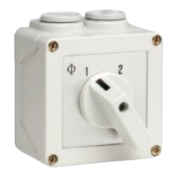
The device described in this manual is a 3-Pole Run/Stop Switch, identified by the model number GA-CTRL-008A. It is designed to dynamically brake a wind turbine, specifically the LE-600 model, though it can be used with other turbines that meet its electrical specifications and are capable of dynamic braking.

Function Description:

The primary function of the run/stop switch is to allow the user to control the operation of a wind turbine by either allowing it to run normally or bringing it to a near stop. This is achieved by manipulating the turbine's power output. In the 'Run' position, the turbine's output flows directly through the switch to the rectifier. In the 'Stop' position, the switch disconnects the turbine's power output from its load and diverts it to a short circuit. This short circuit applies a dynamic braking effect on the permanent magnet alternator of the turbine, causing it to slow down significantly, almost to a stop. This braking function is intended for maintenance purposes only.

Important Technical Specifications:

  • Type: 3-Pole Changeover Switch
  • Model Number: GA-CTRL-008A
  • Electrical Compatibility: Designed for 3-phase Wild AC systems.
  • Voltage Rating: Not exceeding 150 V.
  • Current Rating: Not exceeding 20 A.
  • Wiring: Features 12 screw terminals. Requires shorting links between pins 3 and 7, and pins 7 and 11 for proper operation.
  • Cable Cross-Sectional Area: The wiring diagram indicates the use of 2.5mm² BLK (black) cables for connections to the switch terminals and 30A terminals for the main input/output.
  • Positions:
    • Position 1 (Stop): Dynamically brakes the turbine; turbine may rotate very slowly.
    • Position 2 (Run): Allows turbine output to flow straight through the switch.

Usage Features:

  • Dynamic Braking: Provides a mechanism to quickly slow down the turbine for maintenance.
  • Two-Position Operation: Simple 'Run' and 'Stop' settings for straightforward control.
  • Versatile Mounting: Can be mounted in an enclosure box (supplied) on an internal panel or integrated into an existing panel, requiring a suitable cut-out.
  • Low-Speed Operation Recommendation: The switch should be operated during low wind speeds. Repeated use at high speeds is discouraged as it may cause damage to the turbine head, which is not designed to withstand frequent dynamic braking operations.
  • Safety First: The manual emphasizes reading it thoroughly before assembly, installation, or operation to ensure optimum performance and safety.

Maintenance Features:

  • Braking for Maintenance: The 'Stop' position is specifically designed to bring the turbine to a near stop, facilitating safe maintenance procedures.
  • Wiring Diagram: A detailed wiring diagram is provided to guide correct installation and ensure all connections are made properly. This includes the placement of shorting links and the connection of 3-phase Wild AC from the turbine and 3-phase output to the rectifier.
  • Terminal Security: Users are instructed to ensure all 12 screw terminals of the switch are screwed closed before finally placing the top cover on the switch, which is a key step in ensuring secure and reliable connections.

Safety Precautions Highlighted in the Manual:

The manual stresses the importance of safety during all phases of interaction with the device and associated equipment:

  • Mechanical Safety: Ensure the turbine is suitably restrained and prevented from operating during switch installation.
  • Electrical Safety: Be aware of inherent risks even at low DC voltages generated by wind turbines.
  • Cable Sizing: Always follow cable-sizing guidelines to prevent heat build-up and potential fire hazards from insufficient cross-sectional area.
  • Fusing/Circuit Breakers: Use properly-sized fuses or circuit breakers in battery connections to prevent short-circuit currents.
  • Battery Handling:
    • Batteries can deliver serious current; short circuits can lead to hundreds of Amps, heat build-up, and electrical fires or explosions.
    • Always use insulated electrical tools when working on battery connections.
    • Batteries are heavy; use manual handling tools and an assistant.
    • Keep lead-acid batteries upright to prevent electrolyte spills.
    • Avoid skin contact with acidic electrolyte.
    • Follow manufacturer's safety instructions for lead-acid batteries.
    • Incorrect wiring of the run/stop switch can lead to short circuits across batteries, potentially causing fire or explosion.

The manual serves as a comprehensive guide for the safe and effective use of the 3-Pole Run/Stop Switch, emphasizing both operational procedures and critical safety considerations.

Leading Edge GA-CTRL-008A Specifications

General IconGeneral
BrandLeading Edge
ModelGA-CTRL-008A
CategorySwitch
LanguageEnglish