High Voltage Digital Stepper Drive DM2282 Manual
Page
5
of
7
response, DIR signal should be ahead of PUL signal by 5μs at least. 4-5V when DIR-HIGH,
0-0.5V when DIR-LOW. Please note that rotation direction is also related to motor-driver
wiring match. Exchanging the connection of two wires for a coil to the driver will reverse
motion direction. The direction signal’s polarity is software configurable.
Enable signal: This signal is used for enabling/disabling the drive. In default, high level
(NPN control signal) for enabling the driver and low level for disabling the driver. Usually
left UNCONNECTED (ENABLED). Please note that PNP and Differential control signals
are on the contrary, namely Low level for enabling. The active level of ENA signal is
software configurable.
Fault Signal: OC output signal, active when one of the following protection is activated:
over-voltage, over current, low voltage, phase error and over-temperature. This port can sink
or source 20mA current at 24V. In default, the resistance between FAULT+ and FAULT- is
high impedance in normal operation and become low when DM2282 goes into error.
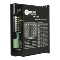
RS232 Communication Port
The RS232 communication port is used to configure the DM2282’s peak current, microstep, active level, current loop parameters and
anti-resonance parameters. See DM driver’s software operational manual for more information.
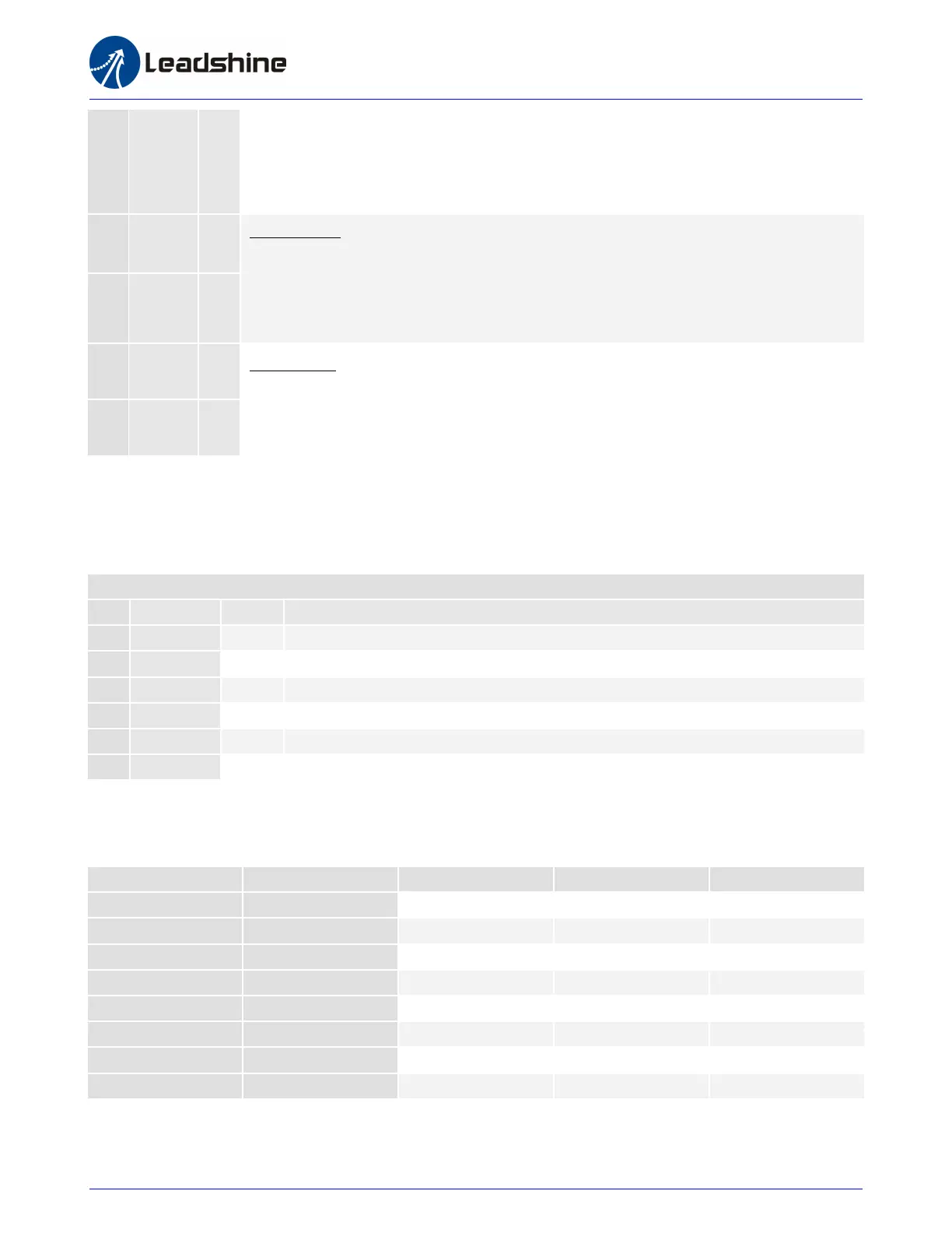
DIP Switch Settings
Dynamic Current
Note: Due to motor inductance, the actual current in the coil may be smaller than the dynamic current setting, particularly under high speed condition.