Leander 950 Series Operator Manual & Warranty
5
Cord Placement
At the rear of the base cover, you will find up to 4 cord attachment sockets for on/off
(red) and uplift peddles (white) as well as the power cord entry socket (black with
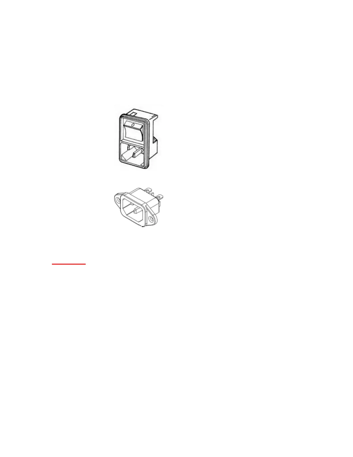
switch). The power cord connects via an international power entry module with a two-
pole switch for activating current (see figure 4). Each of the control pedals attach via
foot switch cord entry modules/ sockets (see figure 4), the cord ends on the controls
provided with the table are color coded to the appropriate connectors.
WARNING: DO NOT PLUG POWER CORD INTO FOOT SWITCH SOCKET OR
FUSE WILL BLOW.
Power Switch/ Power Cord
Entry Module
Figure 5
Foot Switch Cord Entry
Module