5
deployed to raise the windward side of the boat. Also retracting the leeward trim
tab side may help.
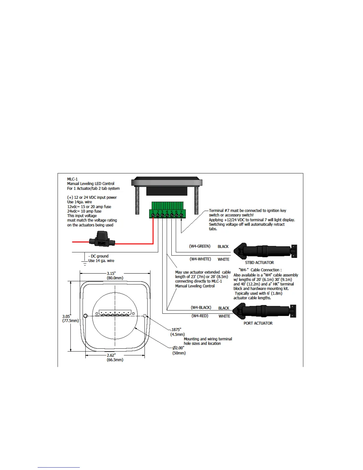
Display Panel Installation & Wiring MLC-1
For MLC-1 (single actuator, single station display only)
Mounting Display Panel:
1. Locate the display panel at the helm where it is convenient to access and view
the LED indicators.
2. The mounting hole diagram has two 3/16” (4.5mm) holes and one 2” (50mm)
as shown below for the two mounting studs and display connector.
3. Mount the display with the washers and nuts provided.
Important: For retrofit installations, always disconnect the wires from the original control
panel before connecting to the MLC. Switch off the main dc circuit breaker before starting
the connection
Wiring Display Panel:
1. Refer to wiring diagram as shown above for the MLC-1 wiring connections.
2. The red (+12vdc or +24vdc) wire from the boat’s fuse panel and black battery
negative wires should be a minimum size of 14 AWG (2.5mm²).
3. Important: DC voltage source connected to MLC switch must match actuator
voltage (first letter in actuator serial A, C or S =12vdc, B or D = 24vdc).