This document outlines the installation and commissioning procedures for the Leelen digital building intercom system. The system is designed for residential communities, integrating video intercom and access control functionalities based on computer network transmission.
System Overview and Functions
The digital building intercom system unifies various components, including enclosure stations, a center guard unit, a central management computer, outdoor stations, digital access control units, and indoor stations, all connected to a computer network. This network facilitates video intercom and access control functions.
Key Functions:
- Access Control: Residents can enter and exit by sweeping access cards at outdoor stations or digital access controllers.
- Video Intercom: Visitors can call homes or the management center from outdoor stations for video intercom and door opening requests. Residents can use indoor stations to monitor outdoor station cameras, call the management guard unit, or intercom with other homes.
- Management Center Capabilities: The management center can call residents' indoor stations for video intercom, manage access cards, send messages to residents, enclosure stations, and building outdoor stations.
- Call Recording: Supports recording of incoming calls, including automatically captured information.
- Visitor Messaging: Allows visitors to leave messages.
- Scalability: The system supports an unlimited number of residents.
- Connectivity: Utilizes RJ45 connections for equipment.
- Data Transmission: Digital network-based data transmission ensures system stability.
System Architecture
A typical project comprises four main sections:
- Enclosure Access Section: Features an enclosure outdoor station for visitors to call indoor stations or the management center, and for residents to access by card. Multiple enclosure entrances can be equipped with digital access controllers and card readers.
- Management Center Section: Typically includes a center management computer and a management guard unit. Management personnel handle access card management, video intercom with residents, and message broadcasting. Larger projects may have auxiliary management centers.
- Building Unit Access Section: Each building unit usually has an outdoor station for visitors to call residents and for residents to access by card. Digital access controllers can be used for additional entrances within a unit.
- Indoor Section: Indoor stations in residents' homes allow answering calls from outdoor stations and the management guard unit, opening doors, intercoming with other residents, checking call records, visitor messages, and notifications.
Cable Description and Requirements
Line Configuration:
- Indoor Station to Network Distributor/Switch:
- L ≤ 90m: UTP5E
- 90m < L ≤ 2km: Multi-mode fiber (number of cores, self-defined)
- L ≤ 20km: Single-mode fiber (number of cores, self-defined)
- Flat Outdoor Station to Network Distributor/Switch:
- L ≤ 90m: UTP5E (serves as secondary video doorbell)
- Building Outdoor Station to Switch:
- L ≤ 90m: UTP5E
- 90m < L ≤ 2km: Multi-mode fiber (number of cores, self-defined)
- L ≤ 20km: Single-mode fiber (number of cores, self-defined)
- Building Outdoor Station to Electric Control Lock: L ≤ 10m: RVV2*1.0
- Building Outdoor Station to Magnetic Lock: L ≤ 10m: RVV2*1.0 (12V-24V)
- Guard Unit to Central Core Switch:
- L ≤ 90m: UTP5E
- 90m < L ≤ 2km: Multi-mode fiber (number of cores, self-defined)
- L ≤ 20km: Single-mode fiber (number of cores, self-defined)
- Lower-level Network Switch to Central Network Switch: L ≤ 90m: UTP5E
- Enclosure Outdoor Station to Network Switch:
- L ≤ 90m: UTP5E
- 90m < L ≤ 2km: Multi-mode fiber (number of cores, self-defined)
- L ≤ 20km: Single-mode fiber (number of cores, self-defined)
- Power Wire of Indoor Station: L ≤ 30m: RVV2*1.0
- Zone Wire of Indoor Station: L ≤ 30m: RVV3*0.5
- Note: The building intercom device does not support direct fiber, but needs to connect via fiber optical converters.
Requirements for Network Cables:
- Wire Diameter and Resistance: Bare copper wire diameter ≥ 0.51mm². Wire resistance of a single UTP5E wire should be less than 12Ω per 100m; the wires resistance of a case (305m) of UTP5E wires should be controlled to be less than 36Ω.
- RJ-45 Joint Line Sequence: Follows standard T568B. All manufactured UTP5E wires must pass the UTP5E wire on-off test.
Pipeline Construction Requirements
Pipeline Solution:
- Architecture: Recommended as linear. Tree-type, star-type, and bus-type architectures should be minimized or avoided.
- Quality: Networked lines among buildings must be independently laid with steel pipes or racks.
- Diameter: Inner diameter of pipes should be 1.7-2 times the outer diameter of the engineering cable, with as few elbows as possible (preferably not more than 2).
Pipe Material Solution:
- Performance: Wires, interfaces, and plug-ins should have high physical and electrical performance and strong anti-interference.
- Practicability: Easy installation, high cost performance, flexible structure, and extensible plug-in interfaces.
- Flexibility: Rational information interface devices, random pull and plug.
- Easy Management: Convenient maintenance, uniform marks, easy wiring and wire jumping.
System Environment Requirements:
- Wiring: All signal lines must be routed through the weak electrical well, avoiding interference sources. They must comply with national standard GB-50348-2004. Signal lines should not be parallel to strong-current wires (AC 220V), radio frequency lines, CATV cables, or large-signal audio lines. If parallel wiring is unavoidable, maintain a distance greater than 35cm.
- Environmental Factors: Installation sites must be damp-proof and dust-proof, away from acoustic, thermal, optical, and vibrating factors to prevent performance degradation.
Network Configuration Environment:
- RJ45 Manufacturing Standard: International standard T568B.
- Network Address Configuration: Ensure no conflicting IP addresses.
- Communication Transmission Distance: Maximum UTP5E transmission distance is 90m. For lengths exceeding 90m, optical fiber transmission or switch cascading is required.
- Wire Selection: Use famous brands. Channel DC Loop resistance of all selected wires should be ≤ 25Ω. Refer to "Code for design of comprehensive wiring system project (GB50311-2007)" for specific parameters.
- Pipeline Laying: Maintain necessary distance from electric appliances (motors, power transformers, radio frequency devices). Wired cables cannot be electrified by AC 220V/380V strong-current power supply or laid parallel to radio frequency signal lines (CATV cables, large-signal audio lines). If parallel wiring is inevitable, the distance between parallel wires should be greater than 30cm.
- Network Switches: Select network switches for all layers based on model.
Installation Manual
Attentions Before Installation:
- Site Check: Ensure the installation site is firm and flat.
- Cable Check: Verify all wires and cables are smoothly connected, free of damage or defects.
- Pre-embedded Box/Bottom Case: Ensure the installation site meets requirements, the box is free of deformation, and its edge is not higher than the wall.
Attentions for Installation Process:
- Installation Height: Camera center of the intercom outdoor station is recommended to be 145cm above the ground.
- Environmental Considerations: Do not install devices in wet, water-dropping, hot, cold, strong magnetic, dusty, or corrosive places. Face recognition devices should not be installed in direct sunlight.
- Handling: Never beat or collide the device with hard substances.
- Power: Do not operate the device when it is electrified to prevent electric shock or device damage.
- Screws: Do not overtighten or undertighten screws to avoid damage.
Installation Completion:
- Cleaning: Clean the site and devices. Do not use flammable cleaners such as alcohol or benzene.
- Liquid Avoidance: Do not pour liquid into the product or cause accidents such as electric conduction.
Description of Version:
- This manual is an engineering installation and commissioning guide. In case of inconsistency with the real object or product manual, the real object prevails.
- This manual is customized for current products. New products or revised versions will be updated as soon as possible. Refer to the product manual or contact technicians for unrecorded new products.
- All registered trademarks and product/company names in this manual belong to Leelen and cannot be duplicated or used without consent.
- Some product information in this manual is confidential and copyrighted by Leelen. Leelen reserves the right of final interpretation.
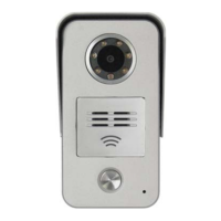
Outdoor Station
Appearances and Main Parameters:
Model No.8 Series:
- Working Voltage: DC12-24V±10%
- Max Power Consumption: ≤4W
- Standby Power Consumption: ≤2.5W
- IP Grade: IP54
- Capacity of Cards: ≤30,000 pcs
- Panel Material: Alum Casting
- Working Temp: -40°C to 70°C
- Operation: Mechanical Pushbutton
- Installation: Surface-mounting/embedded-mounting
- Dimension (mm): 79×148×45
Model No.15 Series:
- Working Voltage: DC12-24V±10%
- Max Power Consumption: ≤6W
- Standby Power Consumption: ≤3W
- IP Grade: IP54
- Capacity of Cards: ≤30,000 pcs
- Panel Material: Alum Casting
- Working Temp: -40°C to 70°C
- Operation: Mechanical Pushbutton
- Installation: Surface-mounting/embedded-mounting
- Dimension (mm): 104×214×50
- Color: Iron Grey
Model No.10 Series:
- Working Voltage: DC12-24V
- Max Power Consumption: ≤8W
- Standby Power Consumption: ≤4W
- IP Grade: IP54
- Capacity of Cards: ≤30,000 pcs
- Panel Material: Alum + Tempered Glass
- Working Temp: -40°C to 70°C
- Operation: Touch Screen
- Installation: Embedded/Iron Gate
- Dimension (mm): 170×386×54
- Embedded Box Dim (mm): 142×358×64
- Color: Aluminum Color
Model No.16 Series:
- Working Voltage: DC18-24V
- Max Power Consumption: ≤8W
- Standby Power Consumption: <4W
- IP Grade: IP54
- Capacity of Cards: ≤30,000 pcs
- Panel Material: Alum + Tempered Glass
- Working Temp: -40°C to 55°C
- Operation: Touch Pushbutton
- Installation: Embedded/Iron Gate
- Dimension (mm): 166×386×52
- Embedded Box Dim (mm): 145×358×60
- Color: Black + Aluminum Color
Installation of Outdoor Station:
Model No.8 Outdoor Station (Embedded Installation):
- Embed pipelines and a pre-embedded box.
- Connect wires, fix the outdoor station and sealing ring on the pre-embedded box with screws.
- Place the front panel on the outdoor station.
- Fasten the front panel and outdoor station with screws.
Model No.15 Outdoor Station (Surface Installation):
- Embed pipelines.
- Fix a sunshade on an iron door using screws.
- Connect wires, place the outdoor station on the sunshade in the direction of the arrow.
- Fasten the outdoor station and the sunshade using screws.
Model No.15 Outdoor Station (Insertion Installation):
- Embed pipelines and the pre-embedded box.
- Connect wires, fix the outdoor station on the pre-embedded box with screws.
Model No.10 Outdoor Station (Embedded Installation):
- Embed pipelines and the pre-embedded box.
- Connect wires, fix the outdoor station on the pre-embedded box with screws.
Model No.16 Outdoor Station (Embedded Installation):
- Embed pipelines and the pre-embedded box.
- Connect wires, place the outdoor station on the pre-embedded box.
- Fasten the outdoor station and the pre-embedded box with screws.
Device Wiring Interface (Model No.8 Outdoor Station):
- Network interface
- Power interface
- 12V output interface
- Signal locking interface
- 485 Interface
- Set Button
- Open button, door magnet monitoring, etc.
Device Wiring Interface (Model No.15 Outdoor Station):
- Battery under-voltage interface
- Fire alarm interface
- Door magnet interface
- Open button
- Power_Rxd, Gnd, Fire-Alarm, Door-State, Open-Door, Gnd
- Power interface
- 12V output
- Signal locking interface
- 485 Interface
- Engineering update interface
- Set button
- Anti-movement monitoring
- Electric connection
- Open button and open
Device Wiring Interface (Model No.10/16 Outdoor Stations):
- Power interface: Power input (red/black wires), supports DC12-24V, SPoE power supply.
- 12V output: 12V + / GND (red/black wires), output ≤750mA.
- RS485 interface: A/B (red/black wires), externally connected to the access card reader.
- Signal locking interface: Relay output switching value (orange/yellow/green wires) with COM / NC / NO. Uses auxiliary power for magnetic lock: negative pole of auxiliary power to COM, NC to negative pole of magnetic lock, positive pole of auxiliary power to positive pole of magnetic lock.
- Network interface: 10/100m self-adaption.
- Exit button: G N D / OPEN_DOOR (black/blue wires).
- Door state: Connected to door magnet device (black/gray wires).
- Fire alarm interface: Connected to switching-value fire alarm signal line (black/purple wires).
- Under-voltage alarm interface: Connected to power supply under-voltage alarm signal line (brown/white wires).
Indoor Stations
Appearances and Main Parameters:
V31:
- Working Voltage: DC12-24V±10% (SPOE support)
- Max Power Consumption: ≤5.5W
- Standby Power Consumption: 1.7W
- Display: 7-inch TFT LCD
- Operation: Capacitive Touch/Capacitive Pushbutton
- Installation: Surface Mounting
- Panel Material: PMMA
- Dimension (mm): 200×140×15.9
V32:
- Working Voltage: DC12-24V±10% (SPOE support)
- Max Power Consumption: ≤5.5W
- Standby Power Consumption: 1.7W
- Display: 7-inch TFT LCD
- Operation: Capacitive Touch/Capacitive Pushbutton
- Installation: Surface Mounting
- Panel Material: PMMA
- Dimension (mm): 220×140×15.9
V33:
- Working Voltage: DC12-24V±10% (SPOE support)
- Max Power Consumption: ≤5.5W
- Standby Power Consumption: 1.7W
- Display: 4.3-inch TFT LCD
- Operation: Capacitive Touch
- Installation: Surface Mounting
- Panel Material: PMMA
- Dimension (mm): 175×114×15.9
E60:
- Working Voltage: DC12-24V
- Max Power Consumption: ≤9 W
- Standby Power Consumption: 3W
- Display: 7-inch TFT LCD
- Operation: Capacitive Touch
- Installation: Surface Mounting
- Panel Material: Tempered Glass
- Dimension (mm): 239×139×20
Installation of Indoor Stations (V31, V32, V33, E60):
- Embed pipelines and a pre-embedded box, then fix the hanging board with screws.
- Connect lines and the indoor station. Align the magnet steel on the back of the indoor station with the convex point on the hanging board, then hang the indoor station.
- Confirm stable hanging and orderly placement.
Device Wiring Interfaces (V31 and V32):
- Anti-dismantling switch
- Power interface
- Network interface
- Alarm Zone interface
- Prevention interface: A8-A1 (zones 8-1), G (ground), 12V (12V output).
Device Wiring Interfaces (V33):
- Power interface
- Alarm zone interface
- Network interface
- Prevention interface: G, A1-A4 (zones 1-4).
Device Wiring Interfaces (E60):
- Anti-dismantling interface
- Power interface
- Alarm interface
- Network switch
- Prevention interface: 12V output, G (ground), A1-A8 (zones 1-8).
Interface Description (Indoor Stations):
- Power interface: Power input, supports DC12-24V, SPoE power supply.
- Network interface: 10/100m self-adaption.
- Alarm Zone interface: Connected to alarm device.
- 7-inch indoor station: 8 zones, 8th zone as doorbell.
- 4.3-inch indoor station: 4 zones, 4th zone as doorbell.
- Wiring diagram of zone infrared sensor: Includes NO, NC, COM, V-, V+ connections with a 4.3KΩ resistor. Normally-off and normally-on infrared probe options.
- Anti-removal interface: Monitors device removal state (4.3-inch indoor station does not have this).
24V Switch Power Supply:
- Input voltage: AC90V-AC240V/50-60Hz
- Maximum input power supply: 0.36Amax
- Output voltage: 24VDC±4V (red + black-)
- Output current: 2.5A
- Static power consumption: 0.5W
- Working temperature: -40°C ~ 55°C
- Protective grade: IP30
- Appearance size: 169×61×124 (mm)
- Installation mode: Wall-typed installation
Digital Network Distributor:
- Working voltage: 18~24V DC
- Static power consumption: 0.5W
- Working temperature: -25°C ~ 70°C
- Capacity: 8 pieces
- Interface: RJ-45 interface/RS485 interface
- Protective grade: IP30
- Appearance color: Iron gray
- Panel material: ABS plastic
- Appearance size: 200×95×30 (mm)
- Installation mode: Wall-typed installation
Digital Access Controller:
- Working voltage: 12~24V DC
- Static power consumption: 1 W
- Working temperature: -40°C ~ 70°C
- Capacity: 30,000 pieces
- Interface: RJ-45 interface/RS485 interface/fire alarm interface
- Protective grade: IP30
- Appearance color: Iron gray
- Panel material: ABS plastic
- Appearance size: 200×95×30 (mm)
- Installation mode: Wall-typed installation
Access Card Reader:
- Working voltage: 12~24V DC
- Static power consumption: 0.77W
- Working temperature: -40°C ~ 70°C
- Interface: RS485 interface
- Protective grade: IP54
- Appearance color: Iron gray
- Panel material: ABS plastic
- Appearance size: 120×86×19.5 (mm)
- Installation mode: Wall-typed installation
Digital IC Card Sender:
- Working voltage: 5V DC
- Maximum power consumption: 0.82W
- Working frequency: 13.56MHz
- Distance to the card sender: ≥2CM (upon specific card)
- Card type: IC card or CPU card
- Working temperature: -25°C ~ 55°C
- Interface: USB interface
- Protective grade: IP30
- Panel material: ABS plastic
- Appearance size: 148×97×35 (mm)
- Installation mode: Desk top
Device Installation:
Installation of 24V Power Supply:
- Fix the power supply in an intelligent box about 160cm above the ground.
Installation Modes of Digital Network Distributor and Digital Access Controller:
Installation of DIN Rail:
- Pull out the slide fastener on the back of the device.
- Install the device on the guide rail rack of the case.
- Fasten the slide fastener to complete installation.
Installation on the Wall:
- Drill two screw holes at a distance of 10cm at proper positions.
- Screw in plastic bases and lock screws.
- Align the hollow spaces on the back of the device with the screw heads, and then hang the device on the screws.
Installation Manner of Access Card Reader:
- Use screws to fix the rear cover on the 86-type pre-embedded box.
- Fasten the front cover on the back of the rear cover.
- Lock the front and rear cover with screws to complete the installation.
Device Wiring:
Wiring Diagram of 24V Switch Power Supply:
- Connect to strong-current socket (220VC) with N and L.
- Reliably grounded.
- Red and black wires for 24V±4V-2.5A output.
Wiring Diagram of Digital Network Distributor:
- Power indicator light.
- Mode selector switch.
- LAN ports (1-8).
- UPLINK port.
- Power interface (+, -).
Wiring Diagram of Access Controller:
- Power interface: (+, -)
- 485 interface: 485A, 485B
- Access interface (1-4): Each includes Open-Door, Gnd, COM, NC, NO.
- FireAlarm interface: Gnd, Fire L.
- LAN interface.
- 10-Core socket: Includes NO, NC, COM, +, -, FIRE, G, G, STATE, OPEN.
- NO: Black
- NC: White
- COM: Grey
- +: Violet
- -: Blue
- FIRE: Green
- G: Yellow
- G: Orange
- STATE: Red
- OPEN: Brown
- Access control (A, B): Red, Black.
Center Guard Unit (Model No.5)
Appearances and Main Parameters:
- Technical parameters:
- Working voltage: DC12-24V±10%
- Maximum power consumption: 8W
- Standby power consumption: <3W
- Operating system: Linux operating system
- CPU: Dual core 1.2GHz
- RAM: 8G
- Flash: 2G
- Screen: 10.1-inch TFT LCD
- Resolution: 1280*800
- Video format: H.264
- Transmission mode: TCP/IP network transmission
- Operating manner: Capacitive touch
Desk Top Installation of the Device:
- Precautions:
- Do not install in a damp environment.
- The desk where the center guide unit is placed should be kept clean and flat.
- The center guide unit should have sufficient distance from other devices to ensure airflow and efficient heat dissipation.
- Do not place any articles on the center guide unit to avoid damage to the display screen and internal elements.
- High Voltage. Danger! Non-professionals may not open the outer casing.
Instructions on Device Wiring:
- Network interface: Connected to the network switch using a straight-through line. Connection method of crystal heads of power cable 586B-586B.
- Power interface: Red Black 18V+ GND.
Commissioning Manual
Precautions for Commissioning:
- Preparations: Collect residential community information, formulate a call code table, and an IP plan.
- Wire Test: Test wires and ensure smooth connections.
- Wiring Check: Verify device wiring, especially power supply wiring, and positive/negative poles.
- Power-on Precautions: If abnormalities occur after powering on, immediately cut off power and resolve issues.
- Commissioning Order (within building): Follow "checking, powering on and commissioning layers one by one."
- Commissioning Order (main platform): Follow "checking, powering on and commissioning buildings one by one."
- Safety: When the system is powered on, it is forbidden to replace or wire the device.
Commissioning Flow:
- Start
- Device installation
- Network detection: If line problems, proceed to line processing. If normal, proceed to electrification.
- Electrification of the device
- Collection of building information, Device address planning
- Parameter setting: Device parameters can be independently preset in the machine room.
- Device commissioning: If device problems, proceed to device replacement. If line problems, proceed to line processing.
- Software installation
- Software parameter setting: For installation, setting, and commissioning of software, see Software Manual.
- Software commissioning
- Networked commissioning: If line problems, proceed to line processing.
- Commissioning completed
Parameter Planning:
Sub-network Division:
- Before IP planning, determine the number of intercom devices needed. Each device requires an IP address.
- IP Address Types: A, B, and C type networks.
- A-type: E.g., 192.x.x.x. Range: 192.0.0.1~192.255.255.254. Default subnet mask: 255.0.0.0. IP quantity: 16,646,144.
- B-type: E.g., 192.168.x.x. Range: 192.168.0.1~192.168.255.254. Default subnet mask: 255.255.0.0. IP quantity: 65,024.
- C-type: E.g., 192.168.1.x. Range: 192.168.1.1~192.168.1.254. Default subnet mask: 255.255.255.0. IP quantity: 254.
- For residential communities with thousands of apartments, B-type IP addresses are usually selected.
- Example (1,500 homes): IP range 192.168.1.1~192.168.6.254. Subnet mask: 255.255.248.0.
IP Division and Subnet Mask of Device (B-type IP address 192.168.x.x example):
- 1 segment (65024 IPs): Subnet mask 255.255.0.0. Range 192.168.0.1~192.168.255.254.
- 2 segments (32512 IPs each): Subnet mask 255.255.128.0. Ranges 192.168.0.1~192.168.127.254 and 192.168.128.0~192.168.255.254.
- 4 segments (16256 IPs each): Subnet mask 255.255.192.0. Ranges 192.168.0.1~192.168.63.254, 192.168.64.1~192.168.127.254, 192.168.128.0~192.168.191.254, and 192.168.192.1~192.168.255.254.
- 8 segments (8128 IPs each): Subnet mask 255.255.224.0. Ranges 192.168.0.1~192.168.31.254, 192.168.32.0~192.168.63.254, ..., 192.168.192.1~192.168.223.254.
- 16 segments (4064 IPs each): Subnet mask 255.255.240.0. Ranges 192.168.0.1~192.168.15.254, ..., 192.168.224.1~192.168.255.254.
- 32 segments (2032 IPs each): Subnet mask 255.255.248.0. Ranges 192.168.0.1~192.168.7.254, ..., 192.168.248.1~192.168.255.254.
- 64 segments (1016 IPs each): Subnet mask 255.255.252.0. Ranges 192.168.0.1~192.168.3.254, ..., 192.168.252.1~192.168.255.254.
- 128 segments: Not recommended.
Planning of the Call Number of a Device:
Collect Information of a Residential Community:
- Includes quantity of enclosure outdoor stations, buildings, ladder ways, floors per ladder way, houses per floor, entrance machines, and indoor stations per house.
Formulate Rules for the Call Number of a Device:
- Call Number Format: 8 digits, divided into a unit-number section and a home-number section.
- Unit Number: 4 digits (e.g., building 01, unit 01 is 0101).
- Home Number: 4 digits (e.g., floor 8, house 03 is 0803).
- Indoor Station Call Number: Unit number - Home number (e.g., 0101-0803).
- Multiple Indoor Stations in a Home: 9-digit call numbers (Unit number - Home number - Sequence number, e.g., 0101-0803-1).
Formulate Rules for the Call Number of an Outdoor Station:
- Enclosure Outdoor Station: 8-bit. Former four bits usually 8888, latter four bits are sequence number (e.g., 8888-0001).
- Building Outdoor Station: 8-bit. Former four bits are unit number, latter four bits are sequence number starting from 0001 (e.g., 0101-0001).
Formulate Rules for the Call Number (e.g., Model No.15) of a Flat Outdoor Station (Secondary Video Doorbell):
- 8-bit. Former four bits consistent with the unit device number, latter four bits are indoor station number + 8000 (e.g., 0101-8803 for home 03 on floor 8 of unit 01 of building 01).
Rules for the Call Number of the Digital Access Controller:
- 8-digit. Set based on installation position.
- Enclosure: Progressively increased according to enclosure outdoor station rules (e.g., 8888-0003).
- Ladder Way: Progressively increased according to building outdoor station rules (e.g., 0101-0003).
Rules for the Call Numbers of Guard Unit and Management Software:
- Guard Unit: 8-digit. Former four bits usually 9999, latter four bits are sequence number (e.g., 9999-0001).
- Management Software: 8-digit. Former four bits usually 9999, latter four bits progressively increased according to guard unit call number (e.g., 9999-0003 if two guard units exist).
Set Call Modes:
- Users can input a device's call number to call it.
- Outdoor stations can be configured to automatically supplement former digits based on the outdoor station's own call number and the user's input to reduce dialing digits (e.g., 3-bit call number for outdoor station 0101-0001 to call 0101-0803).
- Rules for Call Number:
- XXXX (unit number) - XXXX (home number)
- Unit 01 of building 01 outdoor station: 0101-0001
- Home 0803 indoor station: 0101-0803
- 3-digit contact number: XXXX-0XXX
- Outdoor station: XXXX-0001
- Management guard unit: 9999-0001
- Management software: 9999-0002 (default)
- Contact numbers should follow these rules, using 0 to supplement lacking digits.
Application Cases:
- Residential Community Example: 6 high buildings, 1 unit per building, 30 floors per unit, 4 houses per floor, 1 access at underground floor 1, 2 access doors, 1 management center. Also, 2 villas, each with 2 access doors and 4 indoor stations.
- Indoor stations: 6 (building) x 1 (unit) x 30 (floor) x 4 (house) x 1 (indoor station) = 720.
- Villas: 8 indoor stations and 4 outdoor stations.
- Outdoor stations: 6 (building) x 1 (unit) x 2 (pieces) = 12.
Parameter Planning List of Indoor Stations (Unit 01 of Building 01):
- Floor 1: Homes 1-4, SNs 0101-0101 to 0101-0104, IPs 192.168.1.10 to 192.168.1.13.
- Floor 2: Homes 1-4, SNs 0101-0201 to 0101-0204, IPs 192.168.1.14 to 192.168.1.17.
- Floor 8: Homes 1-4, SNs 0101-0801 to 0101-0804, IPs 192.168.1.38 to 192.168.1.41.
- Floor 30: Homes 1-4, SNs 0101-3001 to 0101-3004, IPs 192.168.1.126 to 192.168.1.129.
Outdoor Station Parameters of Unit 01 of Building 01:
- 1st Floor: SN 0101-0001, IP 192.168.1.2.
- Underground Floor 1: SN 0101-0081, IP 192.168.1.3.
- IP parameters for indoor stations of unit 01 of building 02 can be set in the range 192.168.2.10 to 192.168.2.129.
Villa Parameters:
- Villa 01:
- Indoor stations 1-4: SNs 1111-0001-1 to 1111-0001-4, IPs 192.168.7.10 to 192.168.7.13.
- Outdoor station 01: SN 1111-9001, IP 192.168.7.14.
- Outdoor station 02: SN 1111-8001, IP 192.168.7.15.
- Villa 02:
- Indoor stations 1-4: SNs 1111-0002-1 to 1111-0002-4, IPs 192.168.7.16 to 192.168.7.19.
- Outdoor station 01: SN 1111-9002, IP 192.168.7.20.
- Outdoor station 02: SN 1111-8002, IP 192.168.7.21.
Enclosure Outdoor Station No.:
- Position 1: SN 8888-0001, IP 192.168.8.10.
- Position 2: SN 8888-0002, IP 192.168.8.11.
Center Guard Unit No. and Center PC No.:
- Center guide unit: SN 9999-0001, IP 192.168.8.2.
- Center PC machine: SN 9999-0002, IP 192.168.8.5.
Setting of Public Parameters of a Residential Community:
- Subnet mask of all devices: 255.255.0.0.
- Gateway of all devices: 192.168.1.1.
Description of Commissioning of Guard Unit
Necessary Parameters to be Set:
- Device address: Input "999999" in the engineering setting column to enter the setting interface. Set device number and IP address of the guard unit. Select defaults for other items.
Parameter Setting Method:
- Address setting (required item): Input "999999" to enter the engineering setting interface. Set IP Address, Subnet Mask, Gateway, Device No., Guard Unit No., and Center No.
- Supervision: Fill in the name and address of the outdoor station in the monitor setting column of the guard unit, and save the setting. The outdoor station in the interface can then be monitored.
- Duty: Set the guard unit to on-duty or off-duty state. In off-duty state, incoming calls are transferred to a guard unit of the next level.
- Intercom: On the intercom interface, input the device number to perform intercom.
- SOS Records: Check records of SOS signals initiated by indoor stations.
- Alarm Records: Check records of zone alarms initiated by indoor stations.
Instructions on Commissioning of Outdoor Stations
Instructions on Parameters to be Set on the Outdoor Stations:
- Network IP: Set IP address, gateway, and subnet mask according to planned parameters. Check MAC address.
- Address ID: Set device number, management number, management center number, and outdoor station type according to planned parameters.
Instructions of Parameter Settings:
- Accessing Settings: Input "90+1234*" or press the "Set" key through the "Set" hole on the back to enter the outdoor station system setting interface. "1234" is the default engineering password (can be modified).
- Access card management: Functions for access control configuration, resident card management, property card, registered face recognition, Bluetooth, QR code, etc.
- Network: Set IP address, gateway, subnet mask, and DNS.
- Address: Set Device No., Manager No., Center Computer, and Host Type (1:Unit, 2:Wall).
- Version: Check software version, hardware version, kernel version, face version, Bluetooth version, fingerprint version, and SN information. Check MAC address.
- Time limit: Set unlocking duration, door state monitoring, opening time limit, and start/end time of time-limited services.
- Lock Time(s): 5
- Opening Time(s): 3
- Start Of Time-limited Service: 0
- End Of Time-limited Service: 0
- Dial: Set dialing digits (1-8).
- Volume: Set ringtone volume, intercom volume, prompt volume, capture volume, bell volume.
- Door access control: Set door access control mode (control by the machine itself or by the digital access controller).
- Entrance Guard Control: Select Local Control or Digital Entrance Guard Controller.
- Elevator Control: Set Controller No., Device Location (Overground/Underground).
- Date/time: Set time and date, and automatically synchronize time.
- Screen saver: Set time to enter screen saver mode.
- Password: Set new engineering password and reconfirm. Default is 1234.
- Language: Select language (Chinese Simplified, Chinese Traditional, English).
- One-key-acquire: Press one key to acquire parameters of the device in the configuration software.
- Reset to factory default: Select Yes (device will restart) or No.
Device Commissioning Steps:
- Confirm guard unit number.
- Use "Security" button on outdoor station to call guard unit.
- Guard unit confirms outdoor station number is correct.
- Guard unit answers call and confirms audio/video quality.
- Guard unit unlocks door and confirms door is unlocked.
- All items confirmed, commissioning complete.
Instructions on Indoor Station Commissioning
Necessary Parameters to be Set of the Indoor Station:
- Click the setting key at the right lower corner on the desktop of an extension, select "engineering setting," and input password "999999." Modify device number and IP in the address information column (e.g., 0101-0803 for resident with home number 0803).
Indoor Station Setting Method:
- Settings: Input password "999999" to enter engineering setting interface. Modify device number and IP in the address information column.
- Intercom: On the intercom interface, input the 8-digit number of the called party.
- Video Monitor: Set the number of the outdoor station through video monitoring in the system setting interface (e.g., XXXX-XXXX), save, and then check outdoor station video through the monitoring list.
- Security Management:
- Zone alarm setting: Enter engineering setting, click "Security." Set zone sequence number (1-8), alarm type (Prohibit, permanent, immediate, delay), sensor types (SOS, smoke, gas, IR, door magnet). Click "Return" to save.
- Recommendations: Smoke and SOS buttons as permanent zones; door magnet sensors as external and delay zones; living room infrared sensor as internal and delay zones.
- Alarm parameters: Enter user setting interface (default password 123456), click "Alarm parameters." Set Arm delay time(s) (30), Alarm delay time(s) (30), Alarm repeat time(s) (30), Remove setting (off).
- Absent setting: Check effective zones in absent mode.
- Home setting: Check effective zones in home mode.
- Alarm delay time: Time length for alarming after a zone is triggered (60 seconds, with small allowance).
- Alarm repeat time: Time length for re-triggering within 60s after the zone has been triggered (60 seconds, with small allowance).
- Remove setting: Whether to set an alarm sound when the device is dismantled.
- Elevator control: Set the number of the elevator controller and outdoor station as the address of the elevator controller in "Other parameters" option in engineering setting interface. Indoor station sends control command to elevator controller, and elevator controller receives control command and executes corresponding operations.
Test Steps After Device Parameter Setting:
- Confirm guard unit number.
- Use "Security" button on outdoor station to call guard unit.
- Guard unit confirms outdoor station number is correct.
- Guard unit answers call and confirms audio/video quality.
- Guard unit unlocks door and confirms door is unlocked.
- All items confirmed, commissioning complete.
Web Setting Parameters (Model No.8 and Model No.15 Outdoor Station)
- Access: Open browser (latest 360 browser/QQ browser recommended). Input device IP number (see default device IP table below). Input username "admin" and password "123456/999999/111666."
- Default Device IP:
- Model No.8 outdoor station: 192.168.1.8
- Model No.10 outdoor station: 192.168.1.16
- Model No.15 outdoor station: 192.168.1.15
- Model No.16 outdoor station: 192.168.1.16
- Indoor station: 192.168.1.100
- Note: To avoid IP conflicts with indoor stations, set Model No.15 outdoor station as 0101-8803 (indoor station device No. + 8000).
Web Interface Settings (Example):
- Network/Address: IP Address, Subnet Mask, Gateway, DNS, Device No., Guard Unit No., Service Center No., OS Type, MAC Address, SN Information.
- Entrance: Digital Access Controller Switch, Digital Access Controller Number, Access Control Lock Number, Swiping Card to Arm or Disarm, Management Card Function, The Property Card Patrol Function, Copy Card Prevention Function, Password To Unlock, Network Environment Settings.
- Limited Time Settings: Unlock Time, Door Status Switch, Opening Time, Time-limited Service.
- Display/Volume: Language Settings, Ring Volume, Speech Volume, Ring, Camera Tone.
- Dial/Message Settings: Dialing No., Message Function, Time To Wait For Message Prompt.
- Date/Time Settings: Set Time, Set Date, Set Time Settings (Hour, Min, Sec).
- Unlock Password: New Password, Confirm Password.
- Modify parameters and click "Save."
Installation and Commissioning of Management Software
- Refer to the individual User Manual for installation of the management software.
Commissioning Steps of the Main Platform
- Check if the home alarm, outdoor station, and management software can receive messages from the main platform.
- Check if the outdoor station can call indoor station and if the outdoor station can call the management machine and unlock doors.
- Check if the management software download is jammed.
- Check if the outdoor station can sweep card and unlocks doors.