1
OUT
I N
C
4
3
1
2
5
I1 I2 I3 I4
MOD
F422
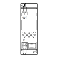
Legend
1. Configurator socket
2. BUS
3. Signalling LED
4. Button for future use
5. OUT clamp
Description
The gateway is an interface that provides communication among different BUS systems.
The interface has two BUS clamps, IN and OUT. On the front is a C key for virtual configu-
ration and a LED for the notification of:
- correct power supply and configuration (ON steady)
- BUS not detected (OFF)
- configuration not detected or incorrect configuration (flashing).
The device may operate in six different modes:
- Physical expansion: can increase the total BUS length or exceed the current draw limit
of 1200 mA for the individual power supply unit.
- Logical expansion: can increase the number of devices of a system, which is 175 (max 11
in rooms defined with A = 0 to 10 and 16 light points with PL = 0 to 15).
Address A = 0, PL = 0 is not permitted.
- Burglar alarm/automation interface: it allows communication between these two sys-
tems.
- Public riser: it provides alarm event supervision for the common parts of the video door
entry system.
- Galvanic separation: can interface two different functions (eg: Sound System with Au-
tomation).
- Physical separation: brings together the features of the Physical expansion mode and
the Galvanic separation mode. It can be used for systems with devices preset for virtual
configuration.
NOTE: Regardless of the interface mode of use, it must be taken into account that
the two Buses connected constitute at all effects two systems, and, as such, they
must be subjected to all existing sizing and installation rules.
Technical data
Power supply via SCS BUS: 27 Vdc
Operating power supply with SCS BUS: 18 – 27 Vdc
IN clamp current draw: 25 mA
OUT clamp current draw: 5 mA
Dissipated power with max. load: 1 W
Dimensions
Size: 2 DIN modules
With the interface configured in this mode, it will be possible to extend the physical limit
of the maximum length of the BUS, or exceed the limit of 1200 mA delivered by the indi-
vidual power supply, but not the maximum number of actuators (max. 175). The positions
identified with I1 and I2 must not be configured. The “separation address” between the
two buses connected to the interface must instead be defined in positions I3 and I4. Sup-
posing as in the example that I3=3, I4=2:
- On the input BUS (IN) the addresses must go from A=0 / PL=1 and A=3 / PL=1;
- On the output BUS (OUT) the addresses must be between A=3 / PL=3 and A=9 /PL=9 or
the address of the next interface. As it can be seen from the example, all the automation
BUS 1 addresses are lower than that of the interface, while all the automation BUS 2
addresses are higher; the interface address therefore separates all the addresses of which
the complete system might be made up of into two or more blocks.
1) “Physical expansion” operating mode - configurator MOD = 1 -
Configuration
Sockets l1, l2, l3, and l4 are used to uniquely identify, using numerical configurators, the
addresses of the interfaces inside the system.
SCS/SCS
gateway
MQ00280-e-EN 07/06/2014
The interface is configured only with the physical configuration.