EasyManua.ls Logo

LEGRAND WattStopper BZ-150 User Manual

LEGRAND WattStopper BZ-150
6 pages
To Next Page IconTo Next Page
Page #1 background imageLoading...
Page #1 background image
Installation Instructions
BZ-150
Power Pack
SPECIFICATIONS
Voltages ........................................... 120/230/277VAC. 50/60Hz
Load Requirements
Ballast ............................................... 20amp @120/277VAC
Incandescent ............................................ 20amp @120VAC
Motor ...................................................... 1HP @120/240VAC
Output .......................225mA @24VDC (with relay connected)
Low Voltage Input
Control ON ......................................................... 12-24VDC
Hold ON .............................................................. 12-24VDC
Hold OFF ............................................................ 12-24VDC
Manual ON (momentary switch required) .......... 12-24VDC
Operating Temperature ..............................32°-104°F (0-40°C)
Santa Clara, CA 95050
Question and Answer IconNeed help?

Do you have a question about the LEGRAND WattStopper BZ-150 and is the answer not in the manual?

LEGRAND WattStopper BZ-150 Specifications

General IconGeneral
BrandLEGRAND
ModelWattStopper BZ-150
CategoryPower Pack
LanguageEnglish

Summary

Specifications

Description

Installation and Wiring

Installation Warning

Crucial safety warning to turn off power at the circuit breaker before installing power packs.

Wiring Connections

Instructions and diagrams for connecting high voltage and low voltage wires for the power pack.

Operation Modes and Wiring Options

Auto ON Mode

Load turns ON automatically via occupancy sensor, Hold ON, or momentary switch.

Manual ON Mode

Load requires manual activation via momentary switch, with sensor override.

Momentary Switch Wiring

Wiring configurations for 2-wire, 3-wire, and multi-button momentary switches.

Low Voltage Inputs and Bi-Level Control

Low Voltage Input Functions

Details on Control ON, Hold ON, Hold OFF, and Manual ON/OFF inputs for controlling the load relay.

Bi-Level Control Configuration

Diagram for configuring two loads (A and B) for bi-level lighting control with manual override.

Protection and Troubleshooting

Over Current Protection

Built-in circuitry protects the +24VDC output from short circuits and thermal overload.

LED Indicator Status

Explains the meaning of different LED states (OFF, blinking, ON) for power and relay status.

Troubleshooting Common Issues

Solutions for problems like lights turning on automatically or not responding to controls.

Ordering Information and Warranty

Product Ordering Details

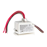
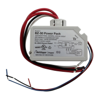
Catalog numbers, descriptions, input voltages, and load ranges for BZ-50 and BZ-150 models.

Warranty Information

Details the five-year warranty for materials and workmanship defects.

Related product manuals