Wattstopper
®
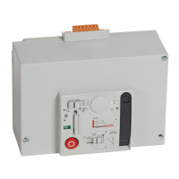
DLM - Digital Input Interface Module
DLM – Module d’interface à entrée numérique
DLM: Módulo de interfaz de entrada digital
Installation Instructions • Instructions d’Installation • Instrucciones de Instalación
No: 25711 – 10/18 rev. 3
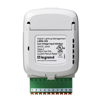
Catalog Number • Numéro de Catalogue • Número de Catálogo: LMIN-104
Country of Origin: Made in China • Pays d’origine: Fabriqué en Chine • País de origen: Hecho en China
LMIN-104-U is BAA and TAA compliant (Product produced in the U.S.)
SPECIFICATIONS
Voltage .................................................................24VDC
Current Consumption ............................................. 20mA
Power Supply ....................Wattstopper Room Controller
Connection to the DLM Local Network ....... 2 RJ-45 ports
Environment ....................................For Indoor Use Only
Operating Temperature ... 32° to 104°F (0° to 40°C)
Storage Temperature .....23° to 176°F (-5° to 80°C)
Relative Humidity ......... 5 to 95% (non condensing)
RoHS compliant, UL2043 Plenum rated
Patent Pending
This unit is pre-set for Plug n’ Go™ operation,
adjustment is suggested.
For full operational details, adjustment and more features
of the product, see the DLM System Installation Guide
provided with Wattstopper room controllers, and also
available at www.legrand.us/wattstopper.
Installation shall be in accordance with all applicable
regulations, local and NEC codes. Wire connections shall
be rated suitable for the wire size (lead and building wiring)
employed.
For Class 2 DLM devices and device wiring: To be
connected to a Class 2 power source only. Do not reclassify
and install as Class 1, or Power and Lighting Wiring.
DESCRIPTION
The LMIN-104 Digital Input Interface Module allows integration of 3rd party devices to the Wattstopper Digital Lighting Management
Local Network (DLM). The LMIN-104 connects to the DLM local network. In addition to On/Off control of loads, it can dim loads up and
down, or send messages such as After Hours, Shed, or Force On to the DLM local network based on external inputs.
OPERATION
The LMIN-104 operates on power from the DLM local network. It also provides input
terminal connections and options for converting input signals from 3rd party devices into
load controlling messages for the DLM system.
Four input terminals are provided for load control, group control, or generating DLM
scenario messages such as Force-ON, Force-OFF, load shedding, and cleaning functions.
Input terminals 1, 2, 3, and 4 are for connection of maintained or momentary switch closure
inputs, or third party logic inputs. Input signals may come from a wide variety of devices
including building automation systems, time clocks, and key switches.
By default, the LMIN-104 inputs accepts 2-wire momentary contacts to control DLM loads. If
2-wire maintained contracts, or 3-wire momentary contacts are needed, they can be set up
using LMCS software.
The LMIN-104 can also be changed via LMCS software so that it can be used as a partition
interface, for connection to an analog Wattstopper occupancy sensor, or for connection
to an remote photocell (functions previously performed by the LMIO-102, LMIO-201 and
LMIO-301 respectively).
NOTE: If an isolated low voltage relay is required, the LMOR-102 provides this functionality.
Using the LMIN-104 with LMCS
The LMIN-104 has three operating modes: Normal, Partition, and Photocell. By default it is set to Normal mode. LMCS-100 software
is required to select another mode. The mode is set for the entire LMIN-104—you can’t have some inputs set to one mode and others
set to another.
While in Normal mode, you can choose between a Switch Input or Sensor Input. When using a switch input, seven Switch modes are
available, which determine the type of message sent to the DLM network. Again, switching selecting a value other than the default
requires LMCS. The available functions are: Load Control (the default, which switches Loads ON/OFF), Normal/After Hours, Load
Shed, Clean Switch, Force On, Force Off, and Key Switch.
If using a sensor input, the LMIN-104 can be used to control Loads or Scenes.
NOTE: In Normal mode, each input is independent and can be set to a different value. For example, you could use inputs 1 and 2 for
momentary switches, input 3 for a maintained switch, and input 4 for an occupancy sensor. However, since a 3 Wire Rocker
Dimmer switch uses two input wires, it requires use of either inputs 1 and 2, or 3 and 4. Therefore, when selecting that value for
input 1 or 3, the corresponding input 2 or 4 will be disabled in LMCS.
GND
Input 1
Input 2
Input 3
Input 4
+24VDC
+24VDC
Photocell In
1 In 1
2 In 2
3 In 3
4 In 4
5 +24
6 +24
8 +24
9 GND
10 P Cell
7 +24
3
4
LED 1
LED 2
Blue LEDs
Config.
Connect to
DLM local network
NOT Ethernet
LED 3
LED 4
24V Overload
2
1