WIREMOLD
®
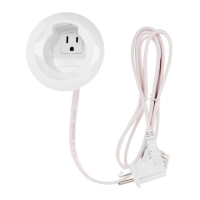
Power Kit
Trousse d’alimentation
Kit de energía
Catalog Number(s) • Numéro(s) de Catalogue • Número(s) de Catálogo: CMK70, CMK75
Country of Origin: Made in China • Pays d'origine: Fabriqué en Chine • País de origen: Fabricado en ChinaA
IMPORTANT:
Please read all instructions before
beginning installation
Legrand electrical systems conform to and
should be properly grounded in compliance with
requirements of the current National Electrical
Code or codes administered by local authorities.
All electrical products may present a possible
shock or fire hazard if improperly installed
or used. Legrand electrical products may
bear the mark of a Nationally Recognized
Testing Laboratory and should be installed
in conformance with current local and/or the
National Electrical Code.
IMPORTANT :
Veuillez lire l'ensemble des
instructions avant de commencer
l'installation.
Les systèmes électriques Legrand sont
conformes au Code National de l'électricité
(National Electrical Code) ou aux codes
locaux en vigueur et doivent être mis à la terre
conformément à ces codes.
Tous les produits électriques peuvent présenter
un risque d'électrocution ou d'incendie s'ils ne
sont pas installés ou utilisés correctement. Les
produits électriques Legrand peuvent porter la
marque d'un laboratoire reconnu et doivent être
installés conformément au Code national de
l'électricité et/ou aux codes locaux en vigueur.
IMPORTANTE:
Lea todas las instrucciones antes
de comenzar la instalación.
Los sistemas eléctricos Legrand cumplen con los
requisitos del Código Eléctrico Nacional (National
Electrical Code, NEC) actual o con los códigos
impuestos por las autoridades locales y deben
conectarse a tierra consecuentemente.
Todos los productos eléctricos pueden presentar
un riesgo de descarga o incendio si se los
instala o utiliza incorrectamente. Los productos
eléctricos Legrand pueden llevar la marca de
un laboratorio de pruebas reconocido a nivel
nacional y se deben instalar conforme al código
local en vigencia o al Código Eléctrico Nacional.
No: 1010497R2 – 0315
Installation Instructions • Notice d’Installation• Instrucciones de Instalación
Tools Needed for Installation • Outils nécessaires pour l’installation •
Herramientas necesarias para la instalación:
1 1/8"
[29mm]
Works with most TV plugs.
Maximum plug width 1 1/8"
S'adapte à la plupart des fiches
de téléviseurs. Fiches d'une
largeur maximale de 1 1/8"
Compatible con la mayoría de los
enchufes de televisores. Ancho
máximo del enchufe 1 1/8"
Check size
Vérifiezla grandeur
Verifique la medida
INSTALLATION • INSTALLATION • INSTALACIÓN:
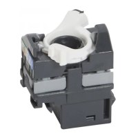
TV Plug
Fiche du téléviseur
Enchufe del televisor
1 1/8"
[29mm]
1
Prior to drilling any holes in the wall, verify the plug from
the television will plug into the top assembly.
Avant de commencer à percer des trous, assurez-vous
que la fiche du téléviseur puisse se brancher dans
l'ensemble supérieur.
Antes de perforar orificios en la pared, verifique que el
enchufe del televisor se conecte a la unidad superior.
CAUTION: Risk of fire and shock. Only
intended for use on 15 ampere
branch circuits.
Attention : Risque d'incendie ou de choc.
Destiné à être utilisé seulement
sur des circuits de dérivation de
15 ampères.
Precaución: Riesgo de incendio y choque
eléctrico. Destinado
únicamente para usar con
circuitos derivados de
15 amperes.