The Leica PaveSmart 3D is a machine control system designed to enhance productivity in paving and milling applications. It operates by continuously measuring the machine's position, elevation, and slopes using robotic total stations (Robots/TPS) or GPS (GNSS) sensors. These measurements are then compared to a computerized 3D design model of the project, generating "Corrections" that represent the necessary machine movements to bring it "online and ongrade." These corrections are transmitted to the machine controller, which regulates the hydraulics, similar to traditional stringline sensors.
Function Description:
The system eliminates the need for physical stringlines, which are prone to errors and logistical challenges on construction sites. It calculates real-time deviations from the 3D design for elevation and steering, allowing for precise machine control. The software supports various machine types, including Curb & Gutter, Milling, Road Paver, Mainline Paver, and Trimmer, with specific profiles and functionalities tailored to each.
Key operational features include:
- Design Map Display: Provides a visual representation of the entire project and the machine's current position. Users can interact with the map to select reference and slope lines for control.
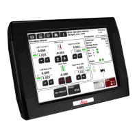
- Corrections Display: Shows the "deviations" of the mold or milling head from the design, indicating the required adjustments for elevation and position. In automatic mode, these deviations should ideally be near zero.
- Information Panel: Displays real-time work progress data such as stationing (chainage), speed, working slope, design slope, milling height, design height, layer offset, and slope offset.
- Sensor Management: Allows configuration and monitoring of connected Robot and GPS sensors, including their status and signal quality.
- Offset Adjustment: Enables setting working offsets relative to selected reference and slope lines, crucial for fine-tuning the machine's position and elevation during production.
- Tuning Dialog: Provides controls to adjust the hydraulic sensitivity for elevation and steering control, optimizing machine response.
- "Here" Function: Available for milling and parallel lane applications, this function allows the operator to reset steering, elevation, or cross-slope corrections to zero by adjusting the corresponding offsets, useful when working along an existing edge.
- Leapfrogging (Swapping Robots): An automated process for transferring measurement of a machine prism from one Robot to another, typically when the machine reaches a predetermined distance from the active robot. This ensures continuous tracking without interruption. The system can automatically select the nearest or furthest measuring robot to be swapped with a spare.
- As-Built Measurements: An integrated function to check elevation and position during production, replacing manual "dipping." Results are recorded and can be exported for quality assurance.
- Backup and Restore: Allows users to create backups of all projects, log files, and software settings, which can be used to restore a previous state or for troubleshooting.
Important Technical Specifications:
- Elevation Accuracy: 5 - 10 mm (approx. 0.02') / 200m (600 ft) for machine position.
- Position Accuracy: 5 - 10 mm (approx. 0.02' - 0.03') / 200 m (600 ft) for machine position.
- GNSS Position, Elevation and Heading Accuracy: 10-25mm (depending on GNSS and slope conditions).
- Maximum Range (recommended): ± 200 m (600 ft).
- Measuring Frequency: 10 Hz.
- Supply Voltage: 12 VDC or 24 VDC.
- Supply Current (max, at 24V DC): 3 A.
- Slope Sensor Specifications:
- Humidity: max. 95% RH, non-condensing.
- Vibration: 10-500 Hz / 5g / ± 0.35 mm (0.014").
- Bump: 25 g / 6 ms.
- Operating Temperature: -10°C to +70°C / +14°F to +158°F.
- Storage Temperature: -25°C to +85°C / -13°F to +185°F.
- Operating Voltage Range: 10 ... 30 Volt DC.
- Current Consumption: approx. 50 mA.
- Principle of Measurement: Liquid sensor.
- Measuring Range: -170% ... +170%, typical -60° ... +60°.
- Internal Resolution: 0.015% 0.01°.
- Linearity: ±0.2% of range.
- Temperature Coefficient (Zero): <0.001% /K <5*10 -4 °/K.
- Temperature Coefficient (Amplifier): <0.02 %/K <1*10 -2 °/K.
- Reproducibility: 0.035% 0.02°.
- Time Constants (T90): min. 0.3 sec settable.
- Sensing Frequency: max. 100 Hz settable.
- CAN Interface: ISO 11898 - 24 V.
- CAN Communication Rate: 125 or 250 kBits/sec.
- Polarity Protection: exists.
- Enclosure Protection: IP 65 (IEC60529).
- MPC1310 (Machine Computer): Ruggedized computer with Windows XP Embedded, touchscreen, milspec connectors for power, CAN, serial (RS232), and USB interfaces.
Usage Features:
- User Interface: The system features a touchscreen interface with clear dialogs and buttons for navigation and settings adjustments. Numeric and text keypads are provided for data entry.
- Project Management: Users can create new projects, select existing ones, and manage layers within stringline jobs.
- Sensor Arrangement: The system supports various sensor configurations, including one or two robotic total stations, or a combination of robot and GPS sensors. It can also integrate up to four Robots or two GPS sensors.
- Working Direction: The working direction (with or against stationing/chainage) can be changed, particularly useful for one-Robot or one-GPS solutions.
- Graphical Views: The Work \ Design \ Graphics dialog offers 3D views and graphical functions like pan, zoom, and rotation of the design.
- Automatic/Manual Line Selection: Reference and slope lines can be selected automatically or manually, depending on the machine profile and controller.
- Hydraulic System Warm-up: Essential to allow the hydraulic system to reach operating temperature before starting work, ensuring consistent machine behavior.
- Shutdown Procedure: Always shut down the MPC1310 using the Exit button to ensure all data and system settings are saved, rather than powering off directly.
Maintenance Features:
- Regular As-Built Checks: Essential to verify product accuracy and identify any changes in machine geometry or sensor performance due to jobsite conditions (temperature, vibration, material consistency).
- Cleaning: Blow dust off components. Use a clean, soft, lint-free cloth, moistened with water or pure alcohol if necessary. Avoid other liquids that may damage polymer components.
- Drying: Damp products, transport containers, foam inserts, and accessories should be dried at temperatures not exceeding 40°C / 108°F. Do not repack until completely dry. Never leave wet components in a sealed carry-case overnight.
- Cables and Plugs: Keep clean and dry. Blow away dirt from connecting cables. Wet connectors must be completely dry before attaching dust caps.
- Storage: Store equipment within specified temperature limits, especially in summer. It is recommended to store the MPC1310 and robots in their supplied cases, protected from weather, during longer breaks.
- Backup: Regularly create backups of all projects, log files, and software settings to prevent data loss and aid in troubleshooting.
- Instrument Setup Quality Check: Perform regular Tiepoint Checks to ensure no undetected movement of robots, especially after long periods of operation or exposure to vibrations, wind, or temperature changes. This involves measuring to predefined fixpoints and verifying accuracy against set tolerances.
- GPS Status Check: Monitor GPS sensor status, including position and height quality, satellite availability, HDOP, VDOP, and heading quality, to ensure reliable operation.