33
ROUTER TABLE OPERATION
R9PLUS Joinery System User Guide
Introduction
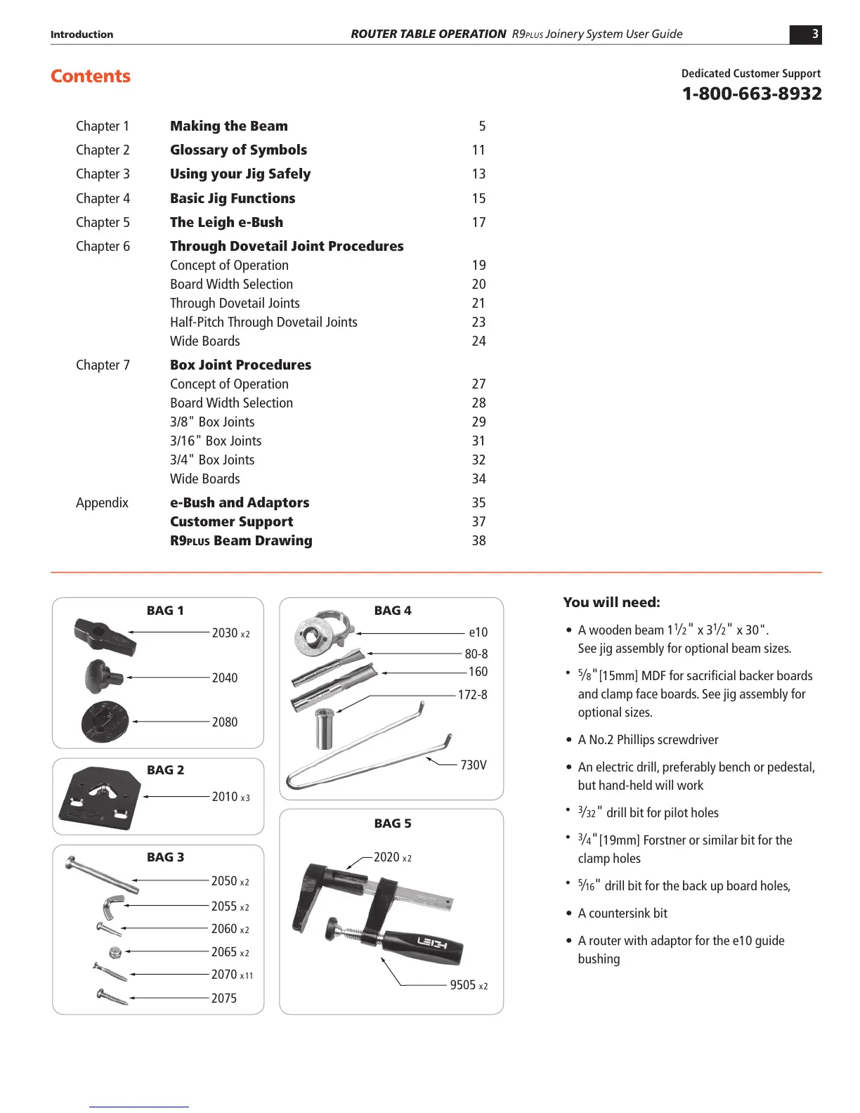
e10
172-8
730V
80-8
160
2030 x 2
2040
2080
2010
x 3
2070 x 11
2075
2065 x 2
2060 x 2
2050 x 2
2055 x 2
2020 x 2
BAG 1 BAG 4
BAG 5
BAG 3
BAG 2
9505 x 2
Contents
You will need:
s A wooden beam 1
1
⁄2"
x 3
1
⁄2"
x 30".
See jig assembly for optional beam sizes.
s 5
⁄8"[15mm]
MDF for sacrificial backer boards
and clamp face boards. See jig assembly for
optional sizes.
s A No.2 Phillips screwdriver
s An electric drill, preferably bench or pedestal,
but hand-held will work
s 3
⁄32"
drill bit for pilot holes
s 3
⁄4"
[19mm] Forstner or similar bit for the
clamp holes
s 5
⁄16"
drill bit for the back up board holes,
s A countersink bit
s A router with adaptor for the e10 guide
bushing
Dedicated Customer Support
1-800-663-8932
Chapter 1 Making the Beam 5
Chapter 2 Glossary of Symbols 11
Chapter 3 Using your Jig Safely 13
Chapter 4 Basic Jig Functions 15
Chapter 5 The Leigh e-Bush 17
Chapter 6 Through Dovetail Joint Procedures
Concept of Operation 19
Board Width Selection 20
Through Dovetail Joints 21
Half-Pitch Through Dovetail Joints 23
Wide Boards 24
Chapter 7 Box Joint Procedures
Concept of Operation 27
Board Width Selection 28
3/8" Box Joints 29
3/16" Box Joints 31
3/4" Box Joints 32
Wide Boards 34
Appendix e-Bush and Adaptors 35
Customer Support 37
R9PLUS Beam Drawing 38
 Loading...