88
ROUTER TABLE OPERATION
R9PLUS Joinery System User Guide
Making The Beam
Chapter 1
A
C
D
B
A
B
B
A
5
/
16
"
1
7
/8
"
5/1
6
"
dia.
x 5/
1
6
"
deep
4
1
/
2
"
[114mm]
[8mm]
[47mm]
[8mm x 8mm]
A
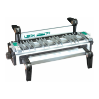
1-13 Turn the assembly upside down. Take a piece of the
predrilled sacrificial board and lay it flush on the template.
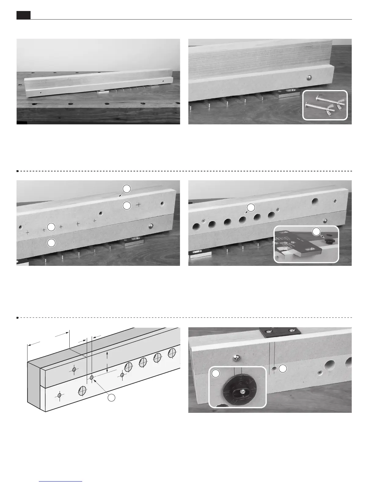
1-15
Place the clamping surface
against the beam
. Be sure
the clamp hole layout marks
are next to the sacrificial board
.
Screw the clamping surface to the beam through the countersunk
holes.
1-17 Side Stop Positioning Create layout lines as indicated
above for the sidestop
. Note: Be precise. Side stop positioning
is very important.
1-14 Using the two
5
⁄16"[8mm] holes as drill guides, drill
two
5
⁄16"[8mm] holes through the beam. Attach the sacrificial
board at the left end with a ¼-20 machine screw and wing nut.
Then move the template to its second position and install the
second screw.
1-16
Clamp Holes Drill all
3
⁄
4
"[19mm] clamp holes
square
to the beam, through the clamping surface and beam. Next,
drill two holes (as per beam drawing),
5
⁄16"[8mm] diameter and
9
⁄16"[14mm] deep, for the table glide
(used for router table
operation only).
1-18 Using a Brad Point or Forstner bit, counter bore a
5
⁄16"[8mm] hole
,
3
⁄8"[9,5mm] deep for the side stop hub.
Then, using a
3
⁄32"[2,5mm] bit, drill a pilot hole for the side
stop mounting screw. Attach the side stop to the beam with the
provided No.8 x 1
1
⁄4"[30mm] round head screw
.
 Loading...