16
16
CSS CSS EASY KSR DIGITAL
6
5
4
3
2
1
7
8
9
10
11
12
18
17
16
15
14
13
19
20
21
22
23
24
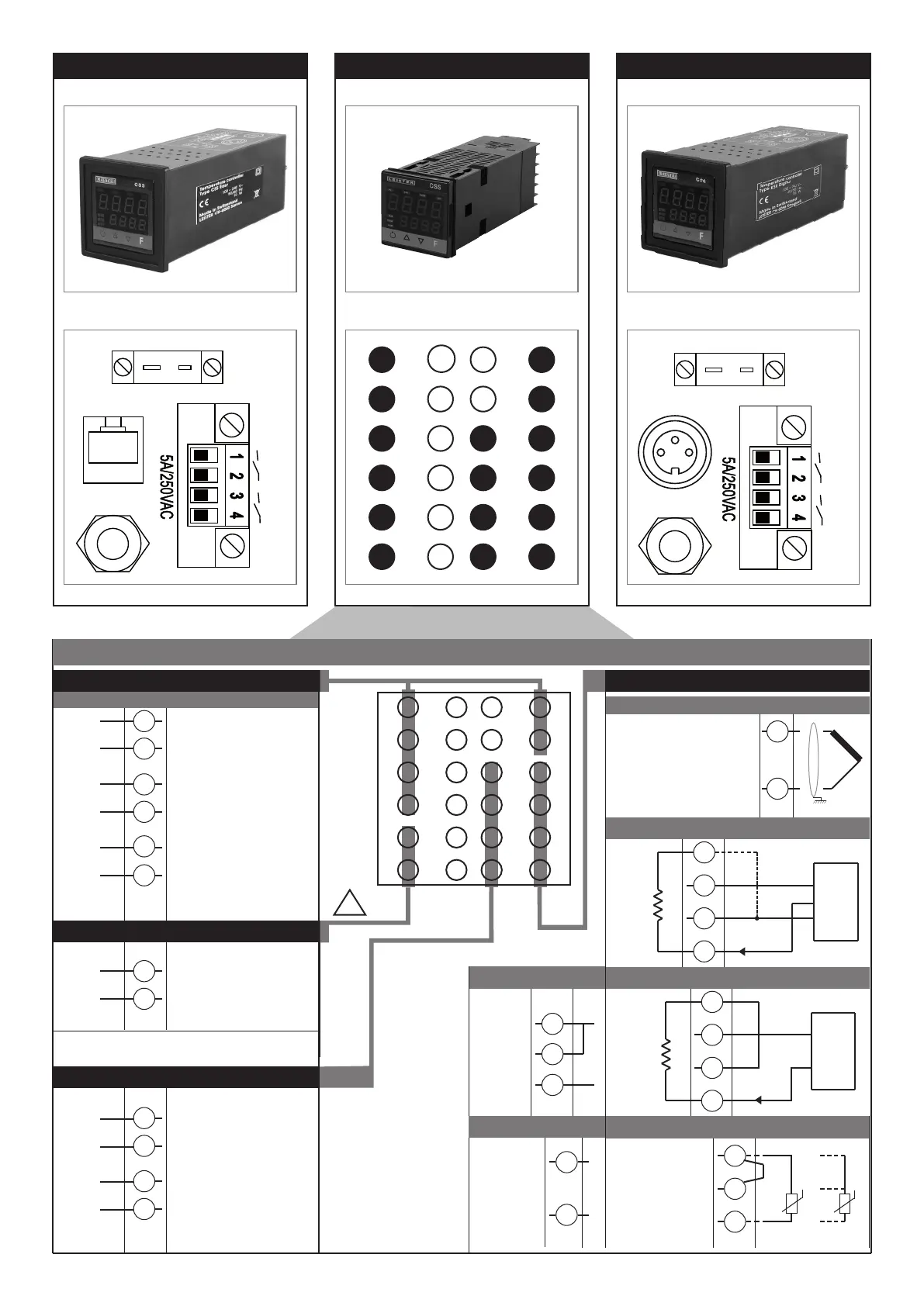
Out 1
Out 3
Leister
I/O
Line
TC
NiCr-Ni
K
+
Out 1
Out 3
Line
TC
NiCr-Ni
K
+
Leister I/O
Alarm output 1 + 2 / Logic output
6
5
4
3
2
1
7
8
9
10
11
12
18
17
16
15
14
13
19
20
21
22
23
24
-
+
Out2
-
+
Out4
+
-
Out1
Power Supply
23
24
~
~
Out3
!
PWR
outputs
4...20mA
Connect at 20mA input
Use wires of adequate
diameter
(min. 1mm
2
)
PT100, JPT100,
PTC, NTC
• Pt100 / PTC / NTC
3
1
2
Pt100 3 wires
PTC / NTC / Pt100
2 leiter
Available thermocouples:
J, K, R, S, T
(B, E, N, L, U, G, D, C custom
linearization is available)
- Observe polarities
- For extensions, use the correct
compensating cable for the type of
TC used
+
-
• TC
2
1
4
2
3
1
+ 24V o 15V
VT
-
+
+
S
-
Ri = 50Ω
4
2
3
1
+ 24V o 15V
VT
-
+
+
-
Ri = 50Ω
T
T
• Linear input for 3-wire transmitter
Inputs
• Linear input for 3-wire transmitter
Linear
input in dc
current
20mA,
Ri = 50Ω
Linear input in dc
voltagel
60mV, 1V
Ri > 1MΩ
5V, 10V
Ri > 10KΩ
2
1
+
-
• Linear signal (I)
4
1
2
-
+
• Linear signal (V)
19
21
20
22
6
5
Configurable output
- Feeding voltage 24 VDC for Leister-
SYSTEM -Elektronik
9
10
- Output signal 4 – 20 mA
(0 – 20 mA / 0 – 10 VDC)
11
12
OUTPWR
Connector pin assignment CSS
- Logic 24V, 10V zu 20mA
- Relais 5A zu 250Vac/30Vdc
(Alarm output 1)
- Relais 5A zu 250Vac/30Vdc
(Alarm output 2)
100 ... 240 VAC ± 10%