22
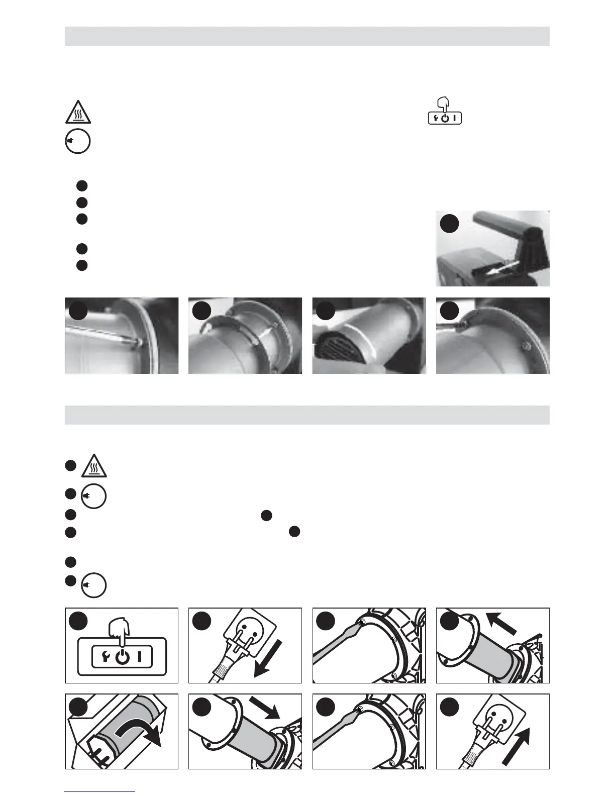
Handle Kit
• The assembly of the handle kit may only be used by trained personnel or under their supervision.
• Handle (13) and protective tube (14) are not included in the scope of supply (see accessories).
Prior to assembly of the handle kit, switch off the unit by the main switch (2) and allow the device
to cool down. Machine switches off automatically.
Disconnect power supply cord (1) form the line/mains.
• Handle kit assembly
Push handle (13) onto the holder (7).
Loosen the four fastening screws (8) (do not remove).
Push the protective tube (14) onto the heating element tube (5)
and move in the opening for fastening screws (8).
Turn the protective tube (14) as far as it will go.
Tighten the four fastening screws (8).
Changing the heating element
1
2
3
4
5
•
C
han
gin
g t
he
hea
tin
g e
lem
en
t m
ay
onl
y be
ca
rri
ed
out
by
tra
ine
d p
ers
onn
el
or u
nd
er t
hei
r su
pe
rvis
ion
.
S
wi
tch
off
th
e m
ain
sw
itc
h
(2)
and
al
low
th
e u
nit
to
coo
l d
ow
n. M
ac
hin
e s
wit
ch
es
off
aut
om
atic
all
y.
D
is
con
ne
ct p
ow
er
su
pp
ly c
ord
(1
) f
orm
th
e l
ine
/ma
ins
.
R
em
ove
th
e fo
ur
fas
ten
ing
sc
re
ws
(8)
.
Re
mo
ve
the
he
ati
ng
ele
me
nt
tub
e (
5)
and
he
ati
ng
ele
me
nt.
T
ake
th
e h
eat
ing
ele
me
nt
out
of
its
pa
cka
gin
g.
A
sse
mb
le
the
he
ati
ng
ele
me
nt a
nd
pu
sh
on
the
he
atin
g
el
em
ent
tu
be
(5)
.
A
sse
mb
le
the
he
ati
ng
ele
me
nt
tub
e (
5)
wit
h fo
ur
fas
ten
in
g s
cre
ws
(8)
.
C
onn
ec
t p
ow
er s
up
ply
co
rd
(1)
to
the
el
ect
rica
l m
ain
s.
The
no
mi
nal
vo
ltag
e i
ndi
cat
ed
on
the
de
vic
e
m
us
t c
orre
sp
ond
to
th
e m
ain
s v
olta
ge
.
1
2
3
4
5
6
7
8
120
230
120
230
120
230
2 3 4 5
1
1 2 3 4
5 6 7 8
 Loading...