Do you have a question about the LEM Hurricane H400S and is the answer not in the manual?
Service requires qualified personnel; unauthorized work voids the warranty.
Components with safety symbols require manufacturer-specified replacements for continued safety.
Emphasizes precautions for handling electrostatic sensitive devices.
Specifies power handling, impedance, and passive crossover frequencies for all models.
Outlines amplifier specifications, frequency response, sensitivity, and maximum SPL for each model.
Covers safety during testing, including earth insulation, capacitor discharge, and load resistors.
Guidance on visual checks for damage and a list of required test instruments.
Detailed steps for checking and adjusting the H100MA model's performance and power supply.
Procedures for checking and adjusting H150A, H200A, and H200MA models.
Procedures for checking and adjusting H300A and H300MA models, including channel and limiter tests.
Detailed steps for checking and adjusting the H350A model's amplifier and power supply.
Procedures for checking and adjusting H350SA and H400SA models, covering various tests.
Provides general advice for diagnosing problems and checking transistors and diodes.
Schematics for the input and amplifier boards of H100MA, H150A, H200A, H200MA models.
Schematics for the input and high-frequency amplifier boards of H350SA and H400SA models.
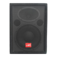
| Configuration | 2-way |
|---|---|
| Impedance | 8 Ohms |
| Power Handling | 400W RMS, 800W peak |
| Sensitivity | 98dB |
| Enclosure Type | Bass Reflex |
| Connectors | Speakon |