55
55
5
to L+, initially set it to 10V/div. 200µS/div. and move the vertical scale from 5 to
20V/div. when required.
13) Press again the ENTER & SEL buttons simultaneously:
a) the COMM led must switch off and after some seconds the SIGNAL/CLIP RED
led must lights up.
b) The display shows "07".
Verify the POWER OUTPUTS:
c) the amplifier LOW & HIGH power outputs must be symmetrical referring to
GND, without any detectable distortion and oscillation.
CH1 LOW AMPLIFIER TEST
15) Verify that the LOW amplifier output signal has an amplitude of 66Vpp.
16) Turn down the generator, connect the 8ohm load resistor and increase the input
signal until the scope screen shows 48Vpp for PEGASUS 212 or 64Vpp for POSEIDON
212 without any detectable distortion.
17) Turn down the generator, then disconnect the 8ohm load resistor and set up the
signal to 0dBu.
18) Switch alternatively the generator frequency from 100Hz, 1KHz and to 10KHz: no
level changes referring to 1KHz level must be detectable.
CH2 HIGH AMPLIFIER TEST
19) Verify that the HIGH amplifier output signal has an amplitude of 32Vpp.
20) Turn down the generator, connect the 8ohm load resistor and increase the input
signal until the scope screen shows the same level without any detectable distor-
tion.
21) Turn down the generator, then disconnect the 8ohm load resistor and set up the
signal to 0dBu.
22) Switch alternatively the generator frequency from 100Hz, 1KHz and to 10KHz: no
level changes referring to 1KHz level must be detectable.
SIGNAL/NOISE RATIO TEST
23) Disconnect all the cables from the module..
24) Press the ENTER & SEL buttons simultaneously:
a) SIGNAL/CLIP GREEN led must lights up and the display shows "07".
Check the following points:
b) Verify that the FAN is idle.
c) Verify that the S/N ratio from 20Hz to 2KHz is below 100dB.
25) Switching OFF the unit.
BURN-IN TEST
• Connect to the amplifier INPUT a pink noise generator.
• Connect two 8ohm resistive loads to the amplifier outputs.
• Switch ON the module and select PRESET no. 01.
• Increase the pink noise level until the SIGNAL/COMP RED led lights up irregularly.
• Run the burn-in test at least 3 hours verifing now and then the right operation.
ACOUSTIC TEST
• After burn-in test the amplifier module must still work properly, verify with an
acoustic test in the speaker box if all works properly and none noise must be still
audible.
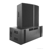
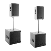
PEGASUS 118 POWER AMPLIFIER MODULE
Initially you have to check the following:
• J3 on INTERFACE BOARD is shorted.
• All JMPx on AMPLIFIER BOARD are opened.
CONTROL PANEL TEST
1) Press and hold the ENTER & SEL buttons simultaneously and switch on the unit,
now the unit is start in "Testing Mode". Check the following points:
a) All the LEDs must light up in sequence.
b) The number "8.8." appears on the display.
2) Press again the ENTER & SEL buttons simultaneously:
a) HUM CANCEL led must light up.
Also check the following points:
b) Press the UP button and verify that "1" appears on the display.
c) Press the DOWN button and verify that "2" appears on the display.
d) Press the ENTER button and verify that "3" appears on the display.
e) Press the SEL button and verify that "4" appears on the display.
EEPROM TEST
3) Press again the ENTER & SEL buttons simultaneously:
a) The NOISE GATE led must light up.
After 50 seconds the display shows:
b) "01" if the EEPROM test passes.
c) "E1" if the EEPROM test fails.
RAM TEST
4) Press again the ENTER & SEL buttons simultaneously:
a) The ANTI-FEEDBACK led must light up.
Wait until display shows:
b) "02" if the RAM test passes.
c) "E2" if the RAM test fails.
FAN TEST
5) Press again the ENTER & SEL buttons simultaneously:
a) the MULTICOMP led must light up.
Immediately:
b) The FAN starts and runs to the maximum speed.
NTC TEST
6) Press again the ENTER & SEL buttons simultaneously:
a) The PRESET led must light up.
b) The FAN stops.
The display shows:
c) "03" if the NTC test passes.
d) "E3" if the NTC test fails.
RS232 SERIAL PORT TEST
7) Insert a RS232 loopback plug in the RS232 port of the power amplifier.
8) Press again the ENTER & SEL buttons simultaneously:
a) The PLUGINS led must be light up.
The display shows:
b) "04" if the RS232 test passes.
c) "E4" if the RS232 test fails.
RS485 IN SERIAL PORT TEST
9) Remove the RS232 loopback plug and choose one of the following:
a) To pass the test without checking IC1 and IC2 on INPUTS & CONTROLS BOARD
extract the flat cable from CN4 on DX BOARD and insert the RS232-485 loopback
micromatch header.
b) Connect the RSC SERIAL CONVERTER between RS232 port and RS485 IN &
OUT ports using the Y cable specified before.
10) Press again the ENTER & SEL buttons simultaneously:
a) The VOLUME led must be light up.
The display shows:
b) "05" if the RS485 IN test passes.
c) "E5" if the RS485 IN test fails.
RS485 OUT SERIAL PORT TEST
11) Press again the ENTER & SEL buttons simultaneously:
a) the COMM led must lights up.
Wait some seconds and the display shows:
b) "06" if the RS485 OUT test passes.
c) "E6" if the RS485 OUT test fails.
FUNCTIONAL TEST
12) Restore or disconnect the RS485 test circuitry.
13) Connect the audio generator set it to 1KHz 0dBu (775mV
RMS
)sinusoidal signal,
level set to zero.
14) Connect the oscilloscope probe 1 clip to L- and tip to L+, initially set it to 10V/div.
200µS/div. and move the vertical scale from 5 to 20V/div. when required.
13) Press again the ENTER & SEL buttons simultaneously:
a) the COMM led must switch off and after some seconds the SIGNAL/CLIP RED
led must lights up.
b) The display shows "07".
Verify the POWER OUTPUTS:
c) the amplifier LOW power output must be symmetrical, without any detectable
distortion and oscillation.
CH1-2 BRIDGE LOW AMPLIFIER TEST
15) Verify that the LOW amplifier output signal has an amplitude of 130Vpp.
16) Turn down the generator, connect the 16ohm load resistor (series of two 8ohm
loads) and increase the input signal until the scope screen shows 130Vpp without
any detectable distortion.
17) Turn down the generator, then disconnect the 16ohm load resistor and set up the
signal to 0dB.
18) Switch alternatively the generator frequency from 1KHz to 100Hz: no level changes
referring to 1KHz level must be detectable.
SIGNAL/NOISE RATIO TEST
19) Disconnect all the cables from the module..
20) Press the ENTER & SEL buttons simultaneously:
a) SIGNAL/CLIP GREEN led must lights up and the display shows "07".
Check the following points:
b) Verify that the FAN is idle.
c) Verify that the S/N ratio from 20Hz to 2KHz is below 100dB.
21) Switching OFF the unit.
BURN-IN TEST
• Connect to the amplifier INPUT a pink noise generator.
• Connect two 8ohm resistive loads to the amplifier outputs.
• Switch ON the module and select PRESET no. 01.
• Increase the pink noise level until the SIGNAL/COMP RED led lights up irregularly.
• Run the burn-in test at least 3 hours verifing now and then the right operation.
ACOUSTIC TEST
• After burn-in test the amplifier module must still work properly, verify with an
acoustic test in the speaker box if all works properly and none noise must be still
audible.
POSEIDON 218 POWER AMPLIFIER MODULE
Initially you have to check the following:
• J3 on INTERFACE BOARD is shorted.
• All JMPx on AMPLIFIER BOARD are opened.
CONTROL PANEL TEST
1) Press and hold the ENTER & SEL buttons simultaneously and switch on the unit,
now the unit is start in "Testing Mode". Check the following points:
a) All the LEDs must light up in sequence.
b) The number "8.8." appears on the display.
2) Press again the ENTER & SEL buttons simultaneously:
a) HUM CANCEL led must light up.
Also check the following points:
b) Press the UP button and verify that "1" appears on the display.
c) Press the DOWN button and verify that "2" appears on the display.
d) Press the ENTER button and verify that "3" appears on the display.
e) Press the SEL button and verify that "4" appears on the display.
EEPROM TEST
3) Press again the ENTER & SEL buttons simultaneously:
a) The NOISE GATE led must light up.
After 50 seconds the display shows:
b) "01" if the EEPROM test passes.
c) "E1" if the EEPROM test fails.
RAM TEST
4) Press again the ENTER & SEL buttons simultaneously:
a) The ANTI-FEEDBACK led must light up.
Wait until display shows:
b) "02" if the RAM test passes.
c) "E2" if the RAM test fails.
FAN TEST
5) Press again the ENTER & SEL buttons simultaneously:
a) the MULTICOMP led must light up.
Immediately:
b) The FAN starts and runs to the maximum speed.
NTC TEST
6) Press again the ENTER & SEL buttons simultaneously:
a) The PRESET led must light up.
b) The FAN stops.
The display shows:
c) "03" if the NTC test passes.
d) "E3" if the NTC test fails.
RS232 SERIAL PORT TEST
7) Insert a RS232 loopback plug in the RS232 port of the power amplifier.
8) Press again the ENTER & SEL buttons simultaneously:
a) The PLUGINS led must be light up.
The display shows:
b) "04" if the RS232 test passes.
c) "E4" if the RS232 test fails.
RS485 IN SERIAL PORT TEST
9) Remove the RS232 loopback plug and choose one of the following:
a) To pass the test without checking IC1 and IC2 on INPUTS & CONTROLS BOARD
extract the flat cable from CN4 on DX BOARD and insert the RS232-485 loopback
micromatch header.
b) Connect the RSC SERIAL CONVERTER between RS232 port and RS485 IN &
OUT ports using the Y cable specified before.
10) Press again the ENTER & SEL buttons simultaneously:
a) The VOLUME led must be light up.
The display shows:
b) "05" if the RS485 IN test passes.
c) "E5" if the RS485 IN test fails.
RS485 OUT SERIAL PORT TEST
11) Press again the ENTER & SEL buttons simultaneously:
a) the COMM led must lights up.
Wait some seconds and the display shows:
 Loading...