EasyManua.ls Logo

LEM PEGASUS 212 User Manual

LEM PEGASUS 212
14 pages
To Next Page IconTo Next Page
Page #1 background imageLoading...
Page #1 background image
11
11
1
Index
Soldering point.
Male connector.
Female connector.
M/F faston connector.
Test point.
Supply voltage. Logic supply ground.
Analog supply ground.
Chassis ground.
Earth ground.
Flag joined with one or more flags
GENERALMUSIC S.p.A. Sales Division: 47842 S.Giovanni in Marignano (RN) ITALY - Via delle Rose, 12
Phone +39(0)541/959511 - Fax +39(0)541/957404 - Internet: www.generalmusic.com
Technical Specification.2
Amplifier Test Procedures & Adjustment.3
OS Upload & Upgrade Instructions, Reset Memory and OS Model Inquiry.
7
8 Input & Controls, Display, Interface, AD/DA Converter and DX Board Schematics.
9
RSC Serial Converter, Block Diagram.
10 Supply and Amplifier Board Schematics.
11 Supply and Amplifier Board Layouts.
12 Spare Part List.
Input & Controls, Display, Interface, AD/DA Converter and DX Board Layouts.
4
Pegasus/Poseidon Test Procedures. 5
with the same signal name inscribed.
ATTENTION
Observe precautions when handling electrostatic sensitive devices.
Notice
Service must be carried out by qualified personnel only. Any tampering carried out by unqualified personnel during the guarantee period
will forfeit the right to guarantee.
For a correct operation of the instrument, after having switched off, be careful to wait at least 3 seconds before switching on again.
To improve the device's specifications, the schematic diagrams may be subject to change without prior notice.
All components marked by this symbol have special safety characteristics, when replacing any of these components use only
manufacturer's specified parts.
The (µ) micro symbol of capacitance value is substituted by U.
The (
) omega symbol of resistance value is substituted by E.
The electrolytic capacitors are 25Vdc rated voltage unless otherwise specified.
All resistors are 1/8W unless otherwise specified.
All switches shown in the "OFF" position. All DC voltages measured to ground with a voltmeter 20KOhm/V.
®
SERVICE MANUAL
code 270282
Digital integrated loudspeaker system
Question and Answer IconNeed help?

Do you have a question about the LEM PEGASUS 212 and is the answer not in the manual?

LEM PEGASUS 212 Specifications

General IconGeneral
BrandLEM
ModelPEGASUS 212
CategorySpeaker System
LanguageEnglish

Summary

Important Safety Notice

General Safety Precautions

Guidelines for safe operation and maintenance of the equipment.

Technical Specifications

Pegasus 212 Specifications

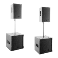
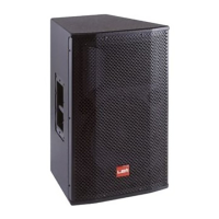
Detailed technical data for the Pegasus 212 loudspeaker system.

Pegasus 118 Specifications

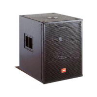
Detailed technical data for the Pegasus 118 loudspeaker system.

Poseidon 212 Specifications

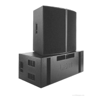
Detailed technical data for the Poseidon 212 loudspeaker system.

Poseidon 218 Specifications

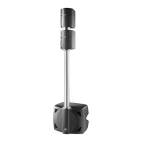
Detailed technical data for the Poseidon 218 loudspeaker system.

Pre-Repair Procedures and Warnings

Important Pre-Repair Notes

Critical information to read before commencing any repair work.

Test Instruments Required

List of essential tools and equipment for amplifier testing.

System Operation and Testing

OS Upload and Upgrade Instructions

Procedure for updating or changing the amplifier's operating system.

Reset Memory and OS Inquiry

How to reset system memory and check the installed OS model.

System Test Setup

Initial setup steps before performing system tests.

Control Panel and Component Tests

Tests for control panel, EEPROM, RAM, Fan, NTC, and serial ports.

Module Specific Amplifier Tests

Tests for Pegasus 118 and Poseidon 218 amplifier modules.

Output Performance and Noise Tests

Tests for amplifier output levels, distortion, and signal-to-noise ratio.

Burn-in and Acoustic Verification

Procedures for burn-in testing and final acoustic validation.

System Communication and Architecture

RSC Serial Converter Details

Information on the RSC Serial Converter and its connections.

System Block Diagram

Overview of the loudspeaker system's internal architecture.

Circuit Schematics

DX Board Schematic

Schematic diagram for the DX Board.

AD/DA Converter Board Schematic

Schematic diagram for the AD/DA Converter Board.

Interface Board Schematic

Schematic diagram for the Interface Board.

Input & Controls Board Schematic

Schematic diagram for the Input & Controls Board.

PCB Layout Diagrams

DX Board PCB Layout

Component layout for the DX Board.

Input & Controls, Display, Interface PCB Layouts

Component layouts for Input/Controls, Display, and Interface boards.

AD/DA Converter Board PCB Layout

Component layout for the AD/DA Converter Board.

Amplifier and Supply Schematics

Power Amplifier Assembly Schematic

Schematic for the main power amplifier assembly.

Supply Board Schematic

Schematic diagram for the power supply board.

Amplifier Board Schematic

Schematic diagram for the amplifier board.

Amplifier and Supply PCB Layouts

Supply & Amplifier Board PCB Layout

Component layout for the Supply and Amplifier boards.

Spare Part List

Related product manuals