44
44
4
CONN1 pin5CONN1 pin5
CONN1 pin5CONN1 pin5
CONN1 pin5
=-5±0.5Vdc=-5±0.5Vdc
=-5±0.5Vdc=-5±0.5Vdc
=-5±0.5Vdc
CONN1 pin3CONN1 pin3
CONN1 pin3CONN1 pin3
CONN1 pin3
=+5±0.5Vdc=+5±0.5Vdc
=+5±0.5Vdc=+5±0.5Vdc
=+5±0.5Vdc
• If one or more voltages don’t correspond, check the rectifiers, capacitors and
transformers disconnecting them from circuitry, refer to schematics.
BIAS ADJUSTMENT:
• Set the generator level at zero, connect the Multimeter across
the OUT1 and TST1
for channel 1 or OUT2 and TST2 for channel 2, then adjust VR100 or VR200 trimmer to
read 10±0.5mVdc.
• This check is made with the heatsink at ambient temperature 25°c.
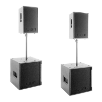
AMPLIFIER CHECK
•
Set up the vertical scale of the oscillo-
scope to 20V./div. then increase the input
signal to 0dBu, corresponding the output
signal increase to 100Vpp for each channel,
the output signal must be symmetrical with-
out visible distortion and oscillation as shown
in
Fig.1
(note: the figure is representative
don't refer to its level). If there is a distor-
tion read the section ADVICES.
•
Set up to zero the input signal, turn off
the amplifier and connect a 8ohm 500W
load on the output finally repeat the previ-
ous check for each channel with the load
attached.
TO AVOID SOME RESISTOR BURNING AB-TO AVOID SOME RESISTOR BURNING AB-
TO AVOID SOME RESISTOR BURNING AB-TO AVOID SOME RESISTOR BURNING AB-
TO AVOID SOME RESISTOR BURNING AB-
SOLUTELY DO NOT CLIP THE AMPLIFIERSOLUTELY DO NOT CLIP THE AMPLIFIER
SOLUTELY DO NOT CLIP THE AMPLIFIERSOLUTELY DO NOT CLIP THE AMPLIFIER
SOLUTELY DO NOT CLIP THE AMPLIFIER
OUTPUTS, OR ALSO DO NOT EXCEED THEOUTPUTS, OR ALSO DO NOT EXCEED THE
OUTPUTS, OR ALSO DO NOT EXCEED THEOUTPUTS, OR ALSO DO NOT EXCEED THE
OUTPUTS, OR ALSO DO NOT EXCEED THE
MAXIMUM INPUT SENSITIVITY OF +4dBu.MAXIMUM INPUT SENSITIVITY OF +4dBu.
MAXIMUM INPUT SENSITIVITY OF +4dBu.MAXIMUM INPUT SENSITIVITY OF +4dBu.
MAXIMUM INPUT SENSITIVITY OF +4dBu.
BANDWIDTH CHECK:
• •
• •
• Sweep the generator frequency from 20Hz to 20KHz, the output level have not
detectable level changes.
ADVICES
• If the input sinewave appears to be distorted during the negative cycle, you can
assume that the problem is located somewhere in the circuitry of the positive rail.
• If the positive cycle appears distorted, you can assume that the problem is in the
circuitry of the negative low rail. Refer to the schematics.
• If you have determinate that the problem is a short on a supply rail, you must check
the output transistors to determine which transistor devices are bad.
• Use a soldering iron to lift one leg of each emitter pin and measure the emitter-
collector resistance on each device.
• Unsolder and lift one leg of each base pin and check the base-collector resistance of
each transistor and replace any that measure as a short.
• If all the transistors are OK, unsolder and lift one leg of each diode and check them.
• Check the circuit board for open foil traces.
• Use the Multimeter as Ohm-meter to check the resistors, particularly the base and
emitter resistors of damaged transistor.
OS UPLOAD & COMPLETE TEST PROCEDURE
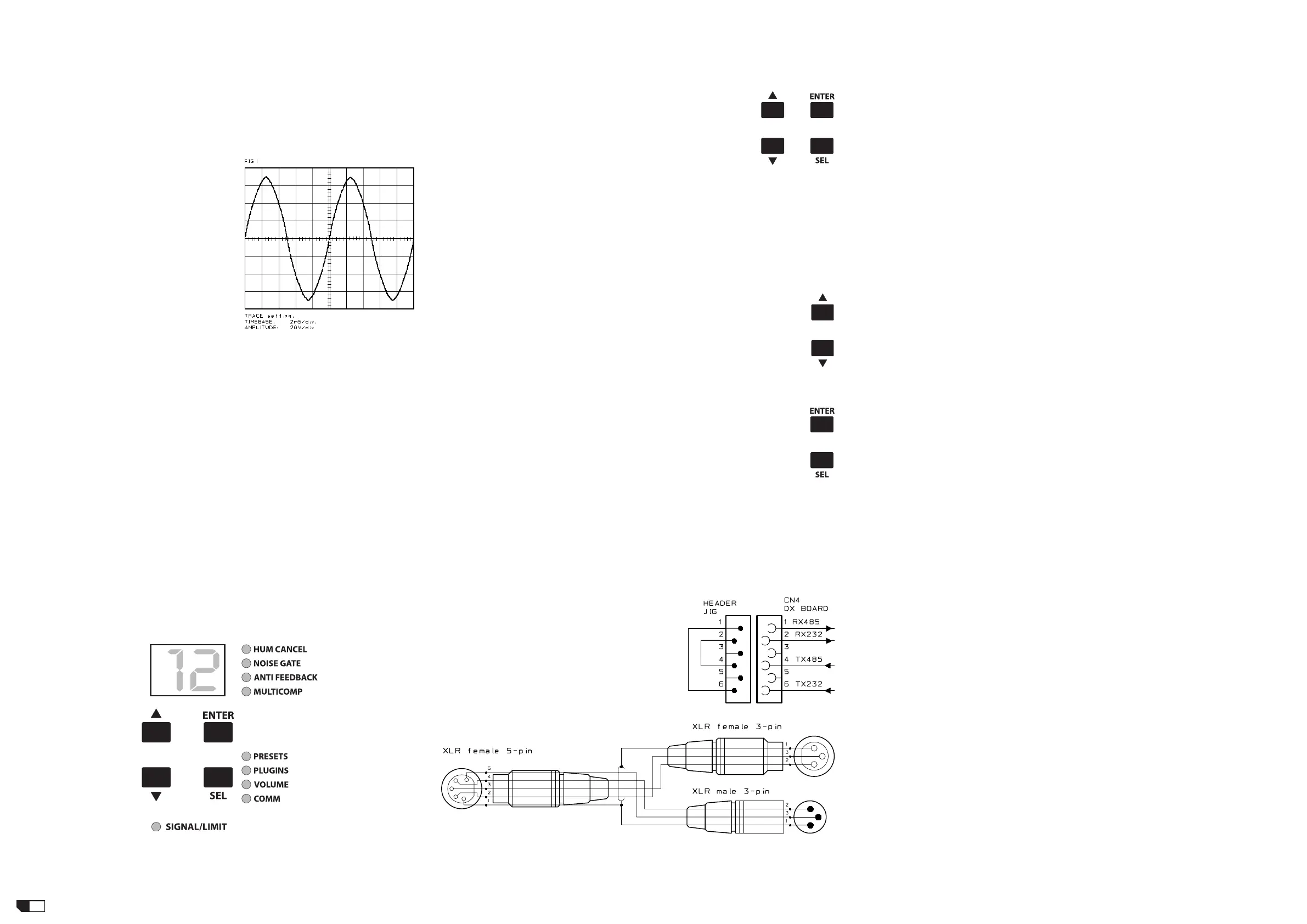
CONTROL PANEL
This figure represent the CONTROL PANEL:
O.S. UPLOAD OR UPGRADE INSTRUCTIONS
• After a replacement of the DX BOARD, before check a specific speaker or when you
want to upgrade the amplifier unit Operating System (O.S.), you have to execute the
following instructions:
1) Run the appropriate O.S. UPGRADE version from the O.S. Upgrade CD.
2) Press and hold all buttons on the amplifier panel then switch
on the unit.
3) The display shows: "Fx" where x is normally E or similar.
4) Check if you have set up the proper COMx port of your PC,
then click on GO.
5) The display shows:
a) FE and HUM CANCEL led lights up.
b) MULTICOMP to COMM leds flash sequentially during the file transfer.
c) F then E and NOISE GATE led lights up.
d) MULTICOMP to COMM leds flash sequentially during the flash memory erase.
e) FE and ANTIFEEDBACK led lights up.
f) MULTICOMP to COMM leds flash sequentially during the flash memory program.
6) Switch off and then switch on the unit.
RESET MEMORY AND OS MODEL INQUIRY
• After any servicing operation, or to know which OS model version is uploaded in
flash memory, or whenever you have doubt about DRAM memory contents or you can
reset all memory data restoring the factory default preset and deleting all user preset.
Execute the following instructions:
1) Press and hold the cursor up and down buttons simultaneously on the
amplifier panel while switch on the unit.
2) The display shows a number that identify which OS model is loaded into
the flash memory, respecting the following table:
[_0] PEGASUS 212 SAT
[_1] PEGASUS 118 SUB
[_2] POSEIDON 212 SAT
[_3] POSEIDON 218 SUB
the SIGNAL/LIMIT leds lights up and some PRESET...COMM leds already lights up.
3) When 01 appears again on the display the unit is restored and operative.
TESTING PROCEDURE
• To start the testing procedure you have to press and hold the ENTER and
SEL buttons simultaneously on the amplifier panel while switch on the unit.
• To complete all test please read all the following advertisements:
SETUP
• The unit must be completely assembled.
• Disconnect all the Speakers.
• The load resistor is disconnected.
• The procedures that follow must be executed subsequently in the order specified.
REMARKS
• If a TEST FAILS the DX BOARD module is idle and until the problem is fixed the
testing procedure cannot continue.
• To pass the RS232 test you have to create a loopback connection between pin 2 and
3 on RS232 port.
• To pass the RS485 test you have to create a loopback connection between RS232
and RS485 ports, two methods are possible:
1) Inserting a Micromatch header with pin1-6
and pin2-4 shorted in CN4 position on DX
BOARD, the test is passed without checking
IC1 and IC2 on INPUTS & CONTROLS BOARD,
see schematic:
2) Using a single RSC Serial Converter (RS232
to RS485) with the supplied RS232 cable and
a self-made Y cable terminated with one XLR
5pin female plug at common side, one XLR
3pin female and one XLR 3pin male plugs at
the other sides, see schematic:
PEGASUS & POSEIDON 212 POWER AMPLIFIER MODULE
Initially you have to check the following:
• J3 on INTERFACE BOARD is opened.
and for PEGASUS-212 only:
• JMP5 and JMP6 on AMPLIFIER BOARD are shorted, all other JMPx are opened.
CONTROL PANEL TEST
1) Press and hold the ENTER & SEL buttons simultaneously and switch on the unit,
now the unit is start in "Testing Mode". Check the following points:
a) All the LEDs must light up in sequence.
b) The number "8.8." appears on the display.
2) Press again the ENTER & SEL buttons simultaneously:
a) HUM CANCEL led must light up.
Also check the following points:
b) Press the UP button and verify that "1" appears on the display.
c) Press the DOWN button and verify that "2" appears on the display.
d) Press the ENTER button and verify that "3" appears on the display.
e) Press the SEL button and verify that "4" appears on the display.
EEPROM TEST
3) Press again the ENTER & SEL buttons simultaneously:
a) The NOISE GATE led must light up.
After 50 seconds the display shows:
b) "01" if the EEPROM test passes.
c) "E1" if the EEPROM test fails.
RAM TEST
4) Press again the ENTER & SEL buttons simultaneously:
a) The ANTI-FEEDBACK led must light up.
Wait until display shows:
b) "02" if the RAM test passes.
c) "E2" if the RAM test fails.
FAN TEST
5) Press again the ENTER & SEL buttons simultaneously:
a) the MULTICOMP led must light up.
Immediately:
b) The FAN starts and runs to the maximum speed.
NTC TEST
6) Press again the ENTER & SEL buttons simultaneously:
a) The PRESET led must light up.
b) The FAN stops.
The display shows:
c) "03" if the NTC test passes.
d) "E3" if the NTC test fails.
RS232 SERIAL PORT TEST
7) Insert a RS232 loopback plug in the RS232 port of the power amplifier.
8) Press again the ENTER & SEL buttons simultaneously:
a) The PLUGINS led must be light up.
The display shows:
b) "04" if the RS232 test passes.
c) "E4" if the RS232 test fails.
RS485 IN SERIAL PORT TEST
9) Remove the RS232 loopback plug and choose one of the following:
a) To pass the test without checking IC1 and IC2 on INPUTS & CONTROLS BOARD
extract the flat cable from CN4 on DX BOARD and insert the RS232-485 loopback
micromatch header.
b) Connect the RSC SERIAL CONVERTER between RS232 port and RS485 IN &
OUT ports using the Y cable specified before.
10) Press again the ENTER & SEL buttons simultaneously:
a) The VOLUME led must be light up.
The display shows:
b) "05" if the RS485 IN test passes.
c) "E5" if the RS485 IN test fails.
RS485 OUT SERIAL PORT TEST
11) Press again the ENTER & SEL buttons simultaneously:
a) the COMM led must lights up.
Wait some seconds and the display shows:
b) "06" if the RS485 OUT test passes.
c) "E6" if the RS485 OUT test fails.
FUNCTIONAL TEST
12) Restore or disconnect the RS485 test circuitry.
13) Connect the audio generator set it to 1KHz 0dBu (775mV
RMS
)sinusoidal signal,
level set to zero.
14) Connect the oscilloscope probe 1 clip to H- and tip to H+, probe 2 clip to L- and tip
 Loading...