Do you have a question about the LEM SWING12 and is the answer not in the manual?
Highlights risks of electric shock, advising not to open the unit and to refer servicing to qualified personnel.
Ensures proper grounding, correct voltage, undamaged cord, and correct switch position before connecting.
Advises on placement to avoid RF interference and how to prevent ground loops using a star system.
Guidelines on handling controls, caring for cables, and avoiding environmental damage to the mixer.
Advises against opening the unit and to contact an assistance center for repairs.
Balanced XLR input for microphones and low impedance signals.
Balanced JACK input for high-level outputs from instruments, excluding microphones.
STEREO JACK connectors for external processing devices like EQs or compressors.
Regulates amplification for mic (-10/-60 dB) and line (+10/-40 dB) inputs.
Provides 15dB boost or cut at 12 kHz with a 'SHELVING' curve.
Provides 12dB boost or cut at 3 kHz with a 'PEAKING' curve.
Provides 12dB boost or cut at 800 Hz with a 'PEAKING' curve.
Hi-PASS filter reduces frequencies below 75 Hz with an 18 dB/Oct. slope to eliminate subsonic frequencies.
Provides 15dB boost or cut at 80Hz with a 'SHELVING' curve.
Controls the PRE-FADER signal level sent to the MON output for independent monitoring mix.
Controls POST-FADER signal level for AUX sends, suitable for external effects. AUX 1 can be switched PRE-FADER.
Regulates stereo position of the signal for main MIX L&R outputs.
Mutes channel to L&R outputs and simultaneously assigns it to MIX B outputs.
Allows listening to the channel via CR/Headphones outputs, with PRE- or POST-FADER selection.
Controls the level of each channel sent to the MIX L&R or MIX B outputs.
JACK connector for STEREO LINE input. Can be used as MONO with a single JACK in LEFT.
XLR-F & RCA connectors for STEREO LINE or MONO MIC signals on SWING 12.
Provides 12dB boost or cut at 2.5 kHz with a 'PEAKING' curve.
Balances LEFT & RIGHT signal levels on main outputs; turning left lowers RIGHT, turning right lowers LEFT.
Unbalanced JACK connectors feeding out the sum of AUX signals, POST-FADER, for outboard effects.
Unbalanced JACK inputs for returning signals directly to MIX L&R or from outboard effects.
Pot for controlling the level of the auxiliary stereo inputs.
Button to assign AUX RETURNS to the MONITOR output, removing them from main MIX L&R.
Unbalanced JACK connectors feeding the sum of MONITOR sends (PRE-FADER) for on-stage monitoring.
Pot for controlling the level of the MONITOR output.
RCA connectors to receive external signals from tape recorders, CD players, DAT, etc.
RCA connectors to send signal from MIX for STEREO recording.
Unbalanced JACK connector sending the sum of MIX L&R signals, POST-FADER.
Pot for controlling the level of the MONO output.
Controls CR & HEADPHONES output levels. Also affects TAPE IN/MIX B when ROUTE TO MIX is pressed.
STEREO JACK connector for stereo headphones with minimum impedance of 200 Ohms.
Selects signal for CR/Headphones: MIX L&R, MIX B, TAPE IN, or ROUTE TO MIX.
Indicates when one or more SOLO buttons are pressed on input channels.
Allows selection of PRE-FADER (PFL) or POST-FADER (AFL) for solo listening and visualization.
LED indicating PFL mode is selected for setting input channel levels.
12-LED BARGRAPHS for signal visualization on Headphones/CR outputs, showing green, yellow, or red (CLIP).
60mm sliders for general volume, controlling signal to MIX L&R outputs and TAPE OUT.
60mm sliders for MIX B volume, controlling signal selected with MUTE/MIX B button.
LED indicating when +48V phantom power is switched on.
LED indicating when the mixer is switched on.
Balanced XLR-M and unbalanced JACK connectors for main program output.
STEREO JACK connectors for processing main program with external devices via 'Y' cables.
Switches MIX L&R output level between +4 dB (line) and -26 dB (mic).
Unbalanced JACK outputs for selected signal (SOLO or CR/PHONES SOURCE) for monitoring or auxiliary bus.
RCA (SWING 12) or JACK (SWING 16) connectors for additional master output of selected channels.
STEREO JACK connectors for processing individual channel signals with external devices.
Button to activate +48V supply for MIC inputs, enabling condenser mics and DI boxes.
The main power switch for the mixer.
Socket for power cord connection and holder for the main fuse, which should be replaced with the same type.
Diagram showing wiring for balanced JACK connectors (TIP, RING, SLEEVE).
Diagram showing wiring for unbalanced JACK connectors (TIP, SLEEVE).
Diagram showing wiring for balanced XLR-M connectors (PIN 1, 2, 3).
Diagram showing wiring for balanced XLR-F connectors (PIN 1, 2, 3).
Diagram showing wiring for RCA connectors (SIGNAL, GROUND).
Diagram illustrating the wiring of a 'Y' cable for STEREO JACK insert points (SEND/RETURN).
Diagram showing typical connections for a Live P.A. setup using the SWING 16 mixer.
Diagram illustrating connections for a home recording setup using the SWING 12 mixer.
Details sensitivity, impedance, and EQ parameters for mono input channels.
Specifies HPF, HIGH, HI-MID, LO-MID, and LOW frequency control ranges and curves.
Details sensitivity, impedance, and EQ parameters for stereo line and mic inputs.
Specifies HIGH, MID, and LOW frequency control ranges and curves for stereo channels.
Details output levels and sensitivities for MIX, Mix B, Control Room, Monitor, Aux, and Tape connections.
Details sensitivity, impedance, and EQ parameters for mono input channels.
Specifies HPF, HIGH, HI-MID, LO-MID, and LOW frequency control ranges and curves.
Details sensitivity and EQ parameters for stereo line inputs.
Specifies HIGH, MID, and LOW frequency control ranges and curves for stereo channels.
Details output levels and sensitivities for MIX, Mix B, Mono, Control Room, Monitor, Aux, and Tape connections.
Covers frequency response, hum & noise, THD, IMD, crosstalk, maximum levels, power supply, weight, and dimensions.
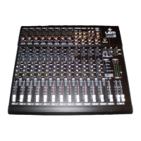
| Channels | 12 |
|---|---|
| Type | Analog Mixer |
| Phantom Power | Yes |
| USB Interface | Yes |
| Aux Sends | 2 |
| Subgroups | 2 |
| Stereo Outputs | 1 |
| Headphone Output | 1 |
| EQ per Channel | 3-band |