Technical Data
Display: 3-
1
/2 digit (1999 ), 7-Segment-Liquid-Crys-
tal-Display, 17 mm high, with illumination
Operating temperature
range: 0° C … + 35° C
Working temperature
range: - 10° C … + 50° C
Storage temperature
range: - 20° C … + 60° C
Reference temperature
range: 23° C ±2° C
Intrinsic error: Refers to the reference temperature
Temperature coefficient: ± 0.1 % of m.v. / K
Operating error: Refers to the operating temperature range
IEC 61557-1
Climatic class: JWG as per DIN 40040 and IEC 654-1;
Relative humidity 65 % annual mean, 85 %
max., no damp.
Protection: IP 40 as per DIN 40050 and IEC 529-2
Safety class: class II ( ) 300 V, install. category III
as per IEC 1010-1 / EN 61010-1,
pollution degree 2.
Test voltage: 3700 V as per IEC 1010-1 / EN 61010-1
Input protection: By software and varistors against voltages
Ueff > 600 V and quick-acting fuses
(6.3 A / 500 V)
Max. voltage to earth: Ueff = 300 V
Clearance / creepage
distances: Correspond to IEC 1010-1 / EN 61010-1
Emission: Class B as per EN 50081-1 and IEC 61326-1
Immunity: Class A as per EN 50082-1 and IEC 61326-1
Quality standard: as per DIN ISO 9001
Auxiliary power: 6 pcs. 1.5 V alkaline manganese batteries
(IEC LR 6) or accu 7.2V / 1500 mAh
(option).
Internal battery for date / time - life 5
years.
Dimensions: 265 x 265 x 90 mm (L x W x H) incl. lid
and compartment for accessories
Weight: approx. 2.3 kg w/o batteries and w/o
accessories
approx. 5.7 kg in carrying case
IrDA
®
Interface (Infrared Data Association) as standard. For easy
PC-communication (remote control, data acquisition, reading of
stored data). RS 232 interface possible as option.
Integrated data memory for 255 data records (approx. 6000
measurement values).
Integrated real time clock with date. Barcode-reader for up to 18
characters useable (option RS 232 interface necessary).
The limits prescribed by the standards can be adapted individually.
A limit infringement is indicated by audible and optical warnings.
Automatic compensation for standard accessories.
Compensation for line extensions up to 5 W possible.
Protective conductor check
Nominal voltage: 50 V … 300 V AC / 15.3 ... 100 Hz
between contact electrode and PE-line
Internal resistance: Approx. 1.5 MW
Phase indication
Nominal voltage: 20 V … 300 V AC / 15.3…420 Hz
Internal resistance: Approx. 400 kW
Admiss. overload: Max. Ueff = 600 V
Note: The voltage of the "L“ and "N“ wire is
measured to "PE“, evaluated and a
symbol indicates the live contact.
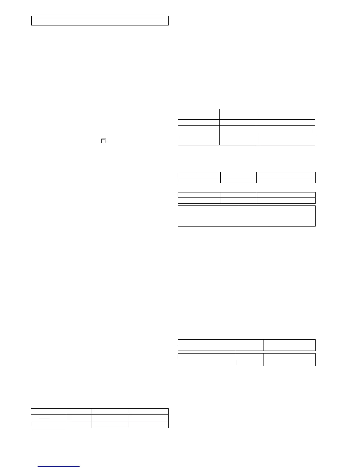
Voltage (DC/ AC), Frequency
Range Resolution Frequency Range Operating error
0..50..440…550V 1 V DC, 15.3…420 Hz ±(1% of mv +1dig)
15.3..99.9..420Hz 0.1…1Hz 5…440 V ±(0.1% of mv +1dig)
Internal resistance: 300…400 kW (L – N – PE)
Residual current operated device check
(FI-RCD / IEC 61557-6)
Measuring functions: RCD-test without tripping
Tripping test with pulses or ramp
(tripping time, tripping current)
Fault voltage
Loop impedance, short-circuit current
(without tripping)
Earth resistance (with probe)
Standard/ selective RCDs
Test currents: IDN x1, x2, x5
positive, negative phase position
positive, negative pulsating DC current
pulses, current steps
Voltage range: 95 ... 145 V, 175 ... 300 V
Frequency range: 15.3...17.5 Hz, 45...65 Hz
Admissible overload: Max. Ueff = 600 V
Function
Intrinsic error of Remark*)
test current
Ramp +/- 10 % 18 steps, 28...125 of I
DN
Pulse,
tripping test 0...+10 % x1/x2/x5 I
DN, 150 mA, 250 mA
Pulse,
non tripping test -10 ... 0 % 0.3 (0.5) I
DN
*) Rated residual current IDN = 10, 30, 100, 300, 500 or
var 6 ... 1000 mA. For function "halfwave/DC" and / or x1/x2/x5
there are some restrictions due to the increased peak current for
higher rated residual currents.
Fault voltage range (U
F
) Resolution Operating error
0.5 … 99.9 V 0.1 V 0…± 8 % of mv. + 2 digit)
Automatic test stop: U
F
>50 V complies with IEC 1010
Tripping time (t
A
) Resolution Operating error
0 … 500 ms (300 ms) 1 ms ± 2 ms
Loop- Resolution Operating error
impedance Z
S
(W)
resp. earth resistance R
A
0.2 W…9.99 kW 0.01 W…10 W ± (10% of mv. + 4 digit)
Test current period as per IEC 1010-1. Limitation of duration
period taking into account the fault voltage as per IEC 61557-6
and IEC 1010-1.
Positive or negative pulsating direct current:
Tripping test - corresponding to the applicable standards which
admit 0.35 ... 1.4 IDN as tripping current. For ramp function the
tripping current is displayed as TRMS of the half-wave current.
Earthing resistance (RA) IEC 61557-5
Measuring method: Current / voltage measurement with probe
Voltage ranges: 95 ... 145 V, 175 ... 300 V, outside
these ranges will not be started.
Frequency ranges: 15.3 ... 17.5 Hz, 45 ... 65 Hz
Admiss overload: Max. Ueff = 600 V before start,
(for > 5 V no start), termination of
measurement for Ueff > 50 V
Measuring time: max. as per IEC 1010, 2 ... 26 periods
Automatic compensation for standard accessories.
Compensation for line extensions up to 5 W possible.
Probe voltage Resolution Operating error
1 ... 70 V 1 V ± (2 % of m.v. + 1 digit)
Measuring range Resolution Operating error
0.01 W...0,15 W...10 kW 0.1 W ... 10 W ± (10% of m.v. + 3 digit)
Test current: 1 A for < 20 W
Max. interference voltage: When US-PE > 20V no measurement
Max. probe resistance: 10 kW, for (RA + Rprobe) > 20 kW no start
Programmable limits: 0.01 W ... 9.99 kW
Insulation resistance (RISO) IEC 61557-2
Measuring method: Current / voltage measurement
Nominal output voltage: 100 / 250 / 500 V DC
Open-circuit voltage: Approx. 105 / 260 / 520 V DC
Nominal current: > 1 mA DC (>2.5 mA DC at 250 V)
Short-circuit current: < 7 mA DC
Admiss. overload: Max. Ueff = 600 V AC; (test is locked)
 Loading...