ZS
Measuring range Resolution Operating error
man: 3 kW...300 MW 1 kW ...1 MW
± (8% of m.v. + 1 digit)
auto: 3 kW ... 10 MW 1 kW ...100 kW
Measuring time: As long as the "START“ button is pressed;
Subsequent automatic discharge of the
test piece via 400 kW
Programmable limit: RISO Limit: 1 kW ... 299 MW (man)
1 kW ... 9.9 MW (auto)
AUTO: Test sequence N - PE, L - PE, L - N,
programmable
Display of the actual measuring voltage:
Measuring range Resolution Operating error
1 ... 520 V DC 1 V ± (8 % of m.v. + 5 Digit)
Internal resistance: Approx. 400 kW (L/N-PE); serves as
discharge resistance for any capacitors in
the measuring circuit.
Max. interference
voltage: Ueff =
1
/
10
of nominal output.
No measurement is started at higher
voltages.
Loop impedance (ZS/R) L-PE or L-N (L) IEC 61557-3
Measuring method: Voltage drop
Nominal voltage: 95...145V, 175...300V,
330...440V (only L-N (L))
Reference voltage: 110/230/400 V or 127/220/380 V AC or
measured voltage
Frequency range: 15.3 ... 17.5 Hz, 45 ... 65 Hz
Test current:
L-PE L-N(L) Voltage range Test current
Zs = 0 W Zs = 200 W
X X 55...145 V 1.4...3.61 A 0.4...0.61 A
X X 175...300 V 1.75...3.0 A 0.58...1 A
X 330...440 V 2.75...3.67 A 1...1.4 A
Measuring range Resolution Operating error
0.07 ... 199 W 0.01 W ...1 W ± (5% of m.v. + 3 digit)
Measuring time: Approx. 4 - 50 periods;
Duration as per IEC 1010
Mains imped. angle: cos j > 0.5
Max. inductance: 5 mH in voltage range > 175 V
Programmable limit: ZS LIMIT: 0.01 ... 199 W
Admiss overload: Max. Ueff = 600 V AC
(measurement is not started outside the
admissible voltage and frequency ranges)
Short-circuit current
Range Display Resolution Operating error
1 A…10 kA 1…40kA 1…10…100 A results from I
K =
U
N
U
N
as selected: 1: 110V, 230V, 400V. 2: 127V, 220V, 380V
resp. 3: measured voltage
Valid ranges for U
N
: 95…145V, 175…300V, 330…440V
(only at Z
S L-N
)
Valid ranges for frequency: 15.3Hz…17.5Hz, 45Hz … 65Hz
Earthelectrode fault voltage (SEV 3569)
Earthelectrode voltage, with probe only
Range Resolution Measuring method
0…U
N 0.1 V U
F
= R
A
. I
K
Detection of rotary field direction IEC 61557-7
Voltage range: 20 ... 440 V AC, 15.3 ... 65 Hz
Admiss. overload: Max. Ueff = 600 V AC
Max. current to earth: < 3.5 mA
Rotary direction display: Symbol for right- / left-handed
Internal resistance: 200 kW ... 400 kW
"Elliptic rotary fields" with two L-conductors and the neutral conduc-
tor can also be tested.
Low resistance measurements (R1kW) IEC 61557-4
Measuring method: Current / voltage measurement with
automatic pole reversal.
Open-circuit voltage: Approx. 20 V DC
Short-circuit current: > 200 mA DC
Admiss. overload: Max. Ueff = 600 V (before START),
no START for > 5 V
Measuring range Resolution Operating error
0.12 ... 2.99...19.9 W...1 kW 0.01...0.1...1 W ± (5 % of m.v. + 3 digits)
Measuring time: Approx. 2 s incl. voltage polarity reversal.
Continous measurement:With depressed START button
Admissible inductance: Max. 5 H
Programmable limit: R
LIMIT
= 0.01 W ... 999 W
Series-mode
interference voltage: Max. 40 V
eff
AC, in case of higher voltage
measurement is terminated.
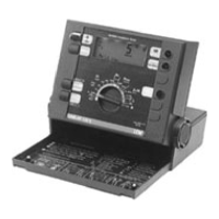
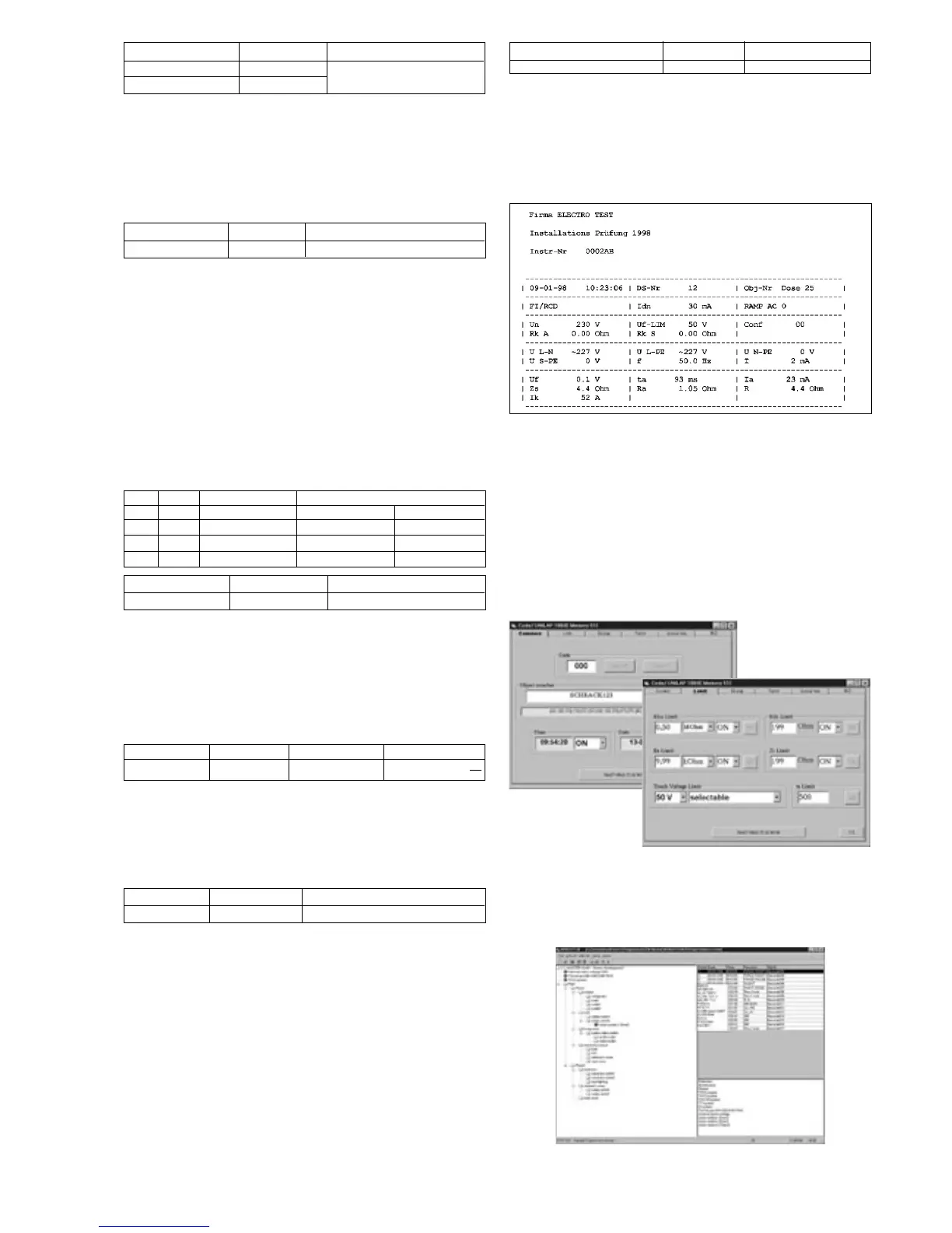
Measuring protocol-print in format A4:
WinSAT 100
the complete system for measured data archiving and protocol tool
for professional electricians.
Application software for UNILAP 100 E and UNILAP 100 XE.
Multilingual, integrated project management and data export.
Can run under Microsoft Windows
®
98 and Windows
®
NT.
Functions
● Code-programming of the UNILAP 100 (X)E
Using tabs, WINSAT100 provides for easy and clear set-up of all
limit values and settings stored inside the device, as well as the
device’s individual configuration with regard to any application
purpose, and to applicable regional regulations.
● Installation descriptions in a tree structure with additional
information can be printed out together with bar codes and used as
a check plan. Same manipulation as Windows
®
explorer,
 Loading...