Do you have a question about the Lenel LNL-300XA and is the answer not in the manual?
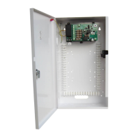
Mount the PSU securely in correct orientation allowing minimum clearance.
Connect mains cable, apply power, and verify green Mains LED is on.
Attach load cable, apply power, and verify load is operating correctly.
Connect EPS and GEN fault outputs to appropriate inputs of control equipment.
Attach battery cables to terminal block, ensuring correct polarity for connections.
Verify tamper switch is closed when lid is closed and open when lid is removed.
Ensure rear tamper is positioned correctly and circuit is closed at control panel.
Understand fault signals and investigate output failures, rectifying before restoring power.
Ensure correct fuse rating and type is used when replacing any fuses.
FireFOM provides individual control of fused outputs via volt-free contact or low-voltage signal.
Configures trigger operation using jumpers for Contact (N/O, N/C) or Voltage modes.
Defines output state (open/closed) and LED status based on mode and trigger inputs.
Details input voltage, frequency, maximum current, and mains input fuse.
Details output voltage, maximum load current, ripple, load output fuses, and overload.
Details battery type, capacity, charging, and fuse protection.
Details enclosure dimensions, weight, material, and battery capacity.
Details operating and storage temperature and humidity ranges.
Describes rating and conditions for GEN Fault, EPS Fault, and Tamper relay contacts.
Details power connections (O/P, -, BATT, -) and fault relay outputs (EPS, GEN).
Unit is for Service Personnel only; periodic testing and battery replacement are key.
Lists European Directives the power supply unit meets: Low Voltage, EMC, WEEE, RoHs2.
Follows WEEE and Battery directives; requires separate battery removal and disposal.
The LNL-300XA 13.8 VDC 4 A Battery Monitoring Switched Mode PSU is a high-efficiency and cost-effective power supply designed for use within a Lenel access control system. It provides a regulated 13.8 VDC output and supplies continuous full-rated current to the load, with a universal mains voltage input. The unit ensures maximum battery life through deep discharge protection, preventing premature battery failure during extended standby periods. It also features two sets of volt-free contacts to signal mains loss, battery faults, and output faults.
This unit is intended for permanent connection only and is not suitable for external installation. It must be fed from a mains power source with a separate, approved disconnect device and a fuse or over-current protection device rated at 3 A maximum. Ensure the disconnect device has appropriate earth fault protection. Before connecting, verify the external disconnect device is OFF. The PSU must be installed according to all relevant safety regulations and must be earthed.
In case of mains loss, battery fault, or GEN fault, the corresponding fault signal contacts will open. If the PSU output fails (e.g., short circuit load, deeply discharged battery), investigate and rectify the cause before restoring power. If fuses need replacement, ensure the correct rating and type are used.
The FireFOM functionality, provided on the daughter card of the power module, allows individual control of the four fused outputs on the 4 A PSU. This is achieved via a volt-free contact (N/O or N/C) or a low-voltage signal (12 VDC/24 VDC). A typical application is to keep the ACU powered during a fire alarm activation that requires power removal from certain system parts (e.g., door lock power removed).
This unit is for use by Service Personnel only; there are no user-serviceable parts inside. Regular maintenance is not required, other than periodic testing and replacement of standby batteries. Refer to the battery manufacturer's documentation for typical/expected battery life and replacement schedule.
This power supply unit meets the essential requirements of the following European Directives:
This product falls within the scope of EU Directives 2012/19/EU Waste Electrical and Electronic Equipment (WEEE) and 2013/56/EU (Battery). At the end of life, the product must be separated from domestic waste and disposed of via an appropriate approved WEEE disposal route in accordance with national and local regulations. Before disposal, any batteries must be removed and disposed of separately via an appropriate approved battery disposal route. Package used batteries safely for onward transport to your supplier, collection point, or disposal facility. Note: Risk of fire or explosion if bare battery wires are allowed to touch.
The LNL-300XA includes fixing positions for a range of OnGuard® controllers and modules, including:
| Brand | Lenel |
|---|---|
| Model | LNL-300XA |
| Category | Power Supply |
| Language | English |