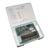
The Lennox Equipment Interface Module (EIM) (10T50) serves as a crucial intermediary between Lennox communicating thermostats (iComfort Wi-Fi® or iComfort® S30) and various HVAC equipment, including both communicating and non-communicating units. It facilitates the integration of different system components, allowing a Lennox communicating thermostat to control a wider range of indoor and outdoor units.
Function Description:
The EIM acts as a translator, converting the communicating signals from a Lennox thermostat (using R, i+, i-, and C terminals) into conventional 24VAC signals that non-communicating HVAC equipment can understand. Conversely, it can also interface between a Lennox communicating furnace and a 24VAC heat pump. This versatility allows homeowners to leverage the advanced features of Lennox communicating thermostats even with existing non-communicating furnaces, air handlers, air conditioners, or heat pumps.
The EIM supports a variety of equipment applications, including single-stage outdoor units with single-stage or variable-stage indoor furnaces. It can manage up to 2-stages of cooling and 3-stages of heat. The module is configured based on the specific system components, with jumper settings determining the unit type (IFC for conventional furnace, HP for heat pump, AHC for conventional air handler) and the number of heat stages.
For dual-fuel operations, the EIM requires additional components, such as the Defrost Air Tempering Kit (67M41). This kit includes a DT1 discharge temperature probe, which is inserted into the furnace air outlet to prevent overheating during heat pump defrost cycles, especially with non-communicating furnaces.
Important Technical Specifications:
- Power Input: The EIM receives 24VAC power through the R and C terminals from the indoor unit transformer.
- Fuse: A 3A fuse (Lennox part number 25J4901) protects the R power input.
- Transformer Rating (VA): The required indoor unit transformer rating varies based on configuration:
- 2-Stage HP, 3-Stage Electric heat: 70 VA
- 2-Stage HP, 2-Stage Furnace (with tempering): 70 VA
- 2-Stage HP, 2-Stage Furnace (without tempering): 50 VA
- 2-Stage AC, 2-Stage Furnace: 40 VA
- Outdoor Air Sensor: The EIM supports an optional X2658 Outdoor Sensor (2 terminals) for ambient temperature readings. The wiring distance for this sensor should not exceed 150 feet (45 meters) when wired with minimum 22AWG (recommended 18AWG) dedicated two-conductor thermostat cable.
- Discharge Air Sensor: An optional 88K38 Discharge Air Sensor (2 terminals) can be used for indoor air diagnostics. For dual-fuel systems, the pre-coil discharge air sensor (DFTS) should be installed downstream of the gas heat exchanger and before the indoor coil, in free airflow, and not exceeding 10 feet when using 18AWG thermostat wire.
- Communicating Terminals: R (24VAC communication power Input), i+ (Communication high - data line), i- (Communication low - data line), C (24VAC communication common power Input).
- Conventional Terminals: W1, W2, W3 (heat outputs), G (indoor blower control), Y2 (2nd-stage compressor output), Y1 (1st-stage compressor output), DS (24VAC dehumidification signal output), H (24VAC humidifier signal output), O (heat pump reversing valve for cooling), B (heat pump reversing valve for heating).
- Dual-Fuel Terminals: DFTS (Pre-coil discharge air temperature sensor), W1-DEF (Defrost signal input), O (Heat Pump Reversing Valve for cooling), B (Heat Pump Reversing Valve for heating).
- Operating Temperature Range: 40°F to 176°F (4°C to 80°C).
- Shipping and Storage Temperature Range: 40°F to 185°F (4°C to 85°C).
- Operating Humidity Range: 10% to 90% non-condensing at 104°F.
- Dimensions: 8" (203mm) wide, 6" (152mm) high, 1-5/8" (42mm) deep.
Usage Features:
- Configuration Setup: The EIM's configuration is determined by system components and set via jumpers.
- Unit Type Jumper: Sets the EIM for Conventional Furnace (IFC), Heat Pump (HP), or Conventional Air Handler (AHC). The factory default is IFC. If the jumper is missing, alarm 130 is activated.
- Heat Stage Jumper: Sets the number of heat stages (electric heat for AHC, gas heat for IFC, compressor stages for HP). Factory default is position 2 (two heat stages). If the jumper is missing, alarm 130 is activated, and the system defaults to single stage.
- Heat Pump Capacity Jumper: Configures the heat pump size (e.g., 1.5, 2.0, 2.5, 3.0, 3.5, 4.0, 5.0 tons) when using a non-communicating heat pump. Factory default is 3.0 tons. If the jumper is missing, alarm 130 is activated.
- LED Indicators:
- RSBUS LED: Flashes when information is being communicated over the RSBus, indicating communication activity.
- Status LED (Green):
- Steady ON: Device sends its start-up message.
- Blinks 3 seconds OFF and 1 second ON: Soft disable state.
- Blinks 2 seconds ON and 2 seconds OFF: Service is being provided (W, Y, or G relay ON, or G input ON).
- Blinks 1 second ON and 1 second OFF: Alarms are present (reviewable on the thermostat screen).
- iComfort Wi-Fi/S30 Commissioning: The EIM integrates with Lennox communicating thermostats for system setup. After installation, the thermostat guides the user through configuring the outdoor unit type (1 or 2-stage) and capacity (18, 24, 30, 36, 42, 48, 60).
- Soft Disable: If the Lennox communicating thermostat detects an unknown control (like an EIM) on the communication bus, it sends a message to enter soft disable mode until properly configured. The EIM will indicate this state by blinking its Status LED (3 seconds OFF, 1 second ON).
- Alert Codes: The EIM transmits error codes to the thermostat, which are displayed on the homeowner notification screen or in the dealer control center. These codes provide diagnostic information and troubleshooting tips.
Maintenance Features:
- Troubleshooting via LED Indicators: The Status and RSBUS LEDs provide immediate visual feedback on the EIM's operational state and communication activity, aiding in initial troubleshooting.
- Alert Code Diagnostics: The thermostat displays detailed alert codes (e.g., 10, 12, 105, 114, 115, 120, 124, 125, 130, 131, 132, 180, 310, 345, 347, 380, 381, 382, 418, 419, 420, 421, 594) that pinpoint specific issues, such as communication loss, sensor problems, relay failures, or incorrect jumper settings. Each alert code comes with a description of the operational state and troubleshooting tips.
- Recommissioning: If jumper positions are changed after the control has been powered up, recommissioning through the Lennox communicating thermostat is required for the changes to be recognized. Similarly, if the EIM is replaced, the thermostat will need to be recommissioned.
- Electrostatic Discharge (ESD) Precautions: The manual emphasizes the importance of taking precautions during installation and service to protect the unit's electronic controls from ESD. This involves neutralizing electrostatic charge by touching hands and tools on an unpainted unit surface before any service procedure.
- Moisture Sensitivity: Controls in the EIM are sensitive to moisture. It is crucial NOT to secure the module to a sheet metal cabinet where moisture may condense during periods of high humidity. Instead, securing the module to a nearby wooden stud is recommended.