Page 2
on an outside wall, on a wall containing water pipes or near
air ducts. Avoid locations that are exposed to discharge air
from registers or radiation from lights, appliances, or the
sun.
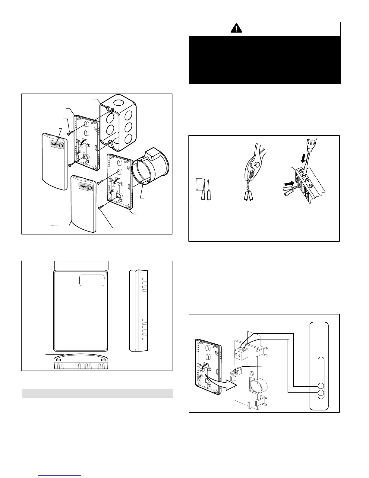
The remote indoor sensor may be installed on a wall, on a
standard utility conduit box using no. 6 (3.5 mm) screws or
on a 60 mm wall outlet box (see figure 2). When installing
directly on a wall, use the type of screws appropriate for the
wall material. See figure 3 for remote indoor sensor
dimensions.
STANDARD UTILITY
CONDUIT BOX
SUBBASE
NO. 6 SCREW
FRONT COVER
FRONT
COVER
SUBBASE
60 MM
WALL
OUTLET
BOX
3.5 MM SCREW
Figure 2. Installing Remote Indoor Sensor on
Standard Utility Conduit Box or 60 mm Wall Outlet
Box
3” (76mm)
4-9/16”
(116mm)
7/8”
(22mm)
Figure 3. Room Sensor Dimensions
WIRING
Attach the wires from the device sensor terminals to the
appropriate remote indoor sensor terminals on the
thermostat (see figure 5).
CAUTION
Improper Electrical Contact Hazard.
Screw type terminal blocks are designed to accept no
more than one 16 AWG (1.31 sq. mm
2
) conductor.
Connect multiple wires that are 16-18 AWG (1.31 to .82
mm
2
) with a wire nut. Include a pigtail with this wire group
and attach the pigtail to the individual terminal block.
Wire the terminal blocks as follows:
1. For single wires, strip 3/16" (5mm); for multiple wires
going into one terminal, strip 1/2 in. (13 mm) insulation
from the conductor.
2. If two or more wires are being inserted into one
terminal, twist the wires together before inserting.
1. STRIP 1/2 IN.
(13 MM)
FROM WIRES
TO BE
ATTACHED AT
ONE TERMINAL.
2. TWIST WIRES
TOGETHER
WITH PLIERS (A
MINIMUM OF
THREE TURNS)
3. CUT TWISTED END OF WIRES TO
3/16 IN. (5 MM) BEFORE INSERTING
INTO TERMINAL AND TIGHTENING
SCREW. THEN PULL ON EACH
WIRE IN ALL TERMINALS TO
CHECK FOR GOOD MECHANICAL
CONNECTION.
E-BUS
CONNECTOR
TERMINALS
Figure 4. Multi-wire Installation
NOTE: When two or more wires are being inserted
into one terminal, be sure to twist them together.
Deviation from this rule can result in improper
electrical contact (see figure 4).
3. Insert the wire in the required terminal location and
tighten the screw to complete the termination.
4. Verify remote indoor sensor wiring per figure 5. Check
that thermistor is in place.
THERMOSTAT (A2)
ZONE SENSOR (RT2)
S1
S2
THERM
ISTOR
Figure 5. Room Sensor Wiring

 Loading...