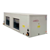
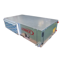
Install the main body
Chart 6
2This chart takes the unit with scroll casing as an example,
which may differ from what you have purchased.
Note:
4
A B C D E F G
Capacity
24000Btu/h
170
18000Btu/h
743
685
170
713
685
927
490
1. Install the dust proof net according to the installation manual;
2. Install the canvas air passage underneath the dust proof net.
Installing the dust proof net and canvas air passage
Pipe Connection
The maximum static pressure in the outside of the unit is 50Pa, the length of the
air pipe attached is determined by this parameter.
30000Btu/h
36000Btu/h
48000Btu/h
60000Btu/h
963
905
170933 905 1140
885
855
199
912
885
1169
1085 1055 1991112
1085
1369
1277 1247 1991308 1277
1500
743
685
713
685
927
A
B
C
D
E
40
45
19
10
19
145
0
0
0
0
Drain point
(Liquid Side fN)
Connecting point of
refrigerant pipe
Connecting point of
refrigerant pipe
(Gas Side fM)
4-10x16 Long hole for hanging
F
G
H
K
L
I
J
H
570
I
290
J
231
K
130
240
L M
16
19
19
19
19
16
N
9.53
12.7
12.7
12.7
12.7
9.53
490
570
490
570
590
670
590
670
590
670
290 231
290 231
330 231
330 231
330 231
130
240
130
240
230
340
230
340
230
340
 Loading...