INSTALLATION OF THE ACCESSORIES
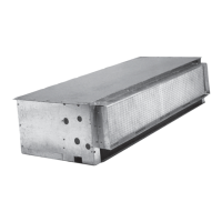
Fig. 9
First of all put the air filter section (SFA) on the unit intake, inserting it into the special rim (male-female) and fixing it
with the galvanised self-tapping screws 4.2x9.5.
Proceed as described above on the delivery end with the connecting flange (FAM).
Put the vibration isolation joint (GAM) on the flange and fix it using the cheese-headed screws M8x16 and hexagon
bolts.
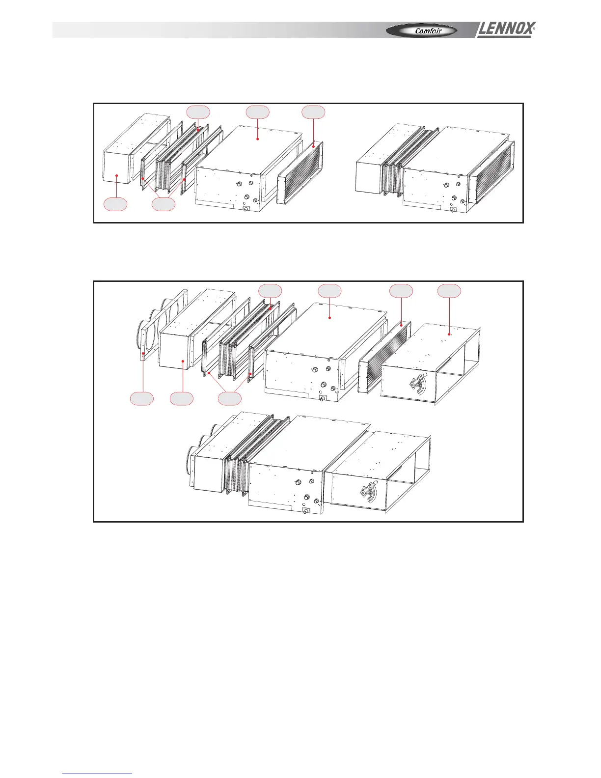
Some examples are given below of assembling the accessories for ducted air treatment units.
Proceed by inserting the manual air intake section (SSP) into the air filter section (SFA) by means of the male-female
coupling.
After having secured it with the self-tapping screws (4.2 x 9.5 galvanised), anchor it to the ceiling as illustrated for the
base unit in figures 4-7.
Put another connecting flange on the vibration isolation joint (GAM) and secure it using cheese-headed screws M8x16
and hexagon bolts.
Insert the straight delivery plenum (PAM) in the connecting flange and fix it using galvanised self-tapping screws 4.2
x 9.5.
Connect the air delivery union with round fittings (BAM) with the procedure described above.
Fig. 10
GAM
PAM FAM
FCC SFA
GAM
PAM FAM
FCC SFA SSP
BAM
INSTALLATION - OPERATING & MAINTENANCE MANUAL
Page 8
 Loading...