UNIT INSTALLATION
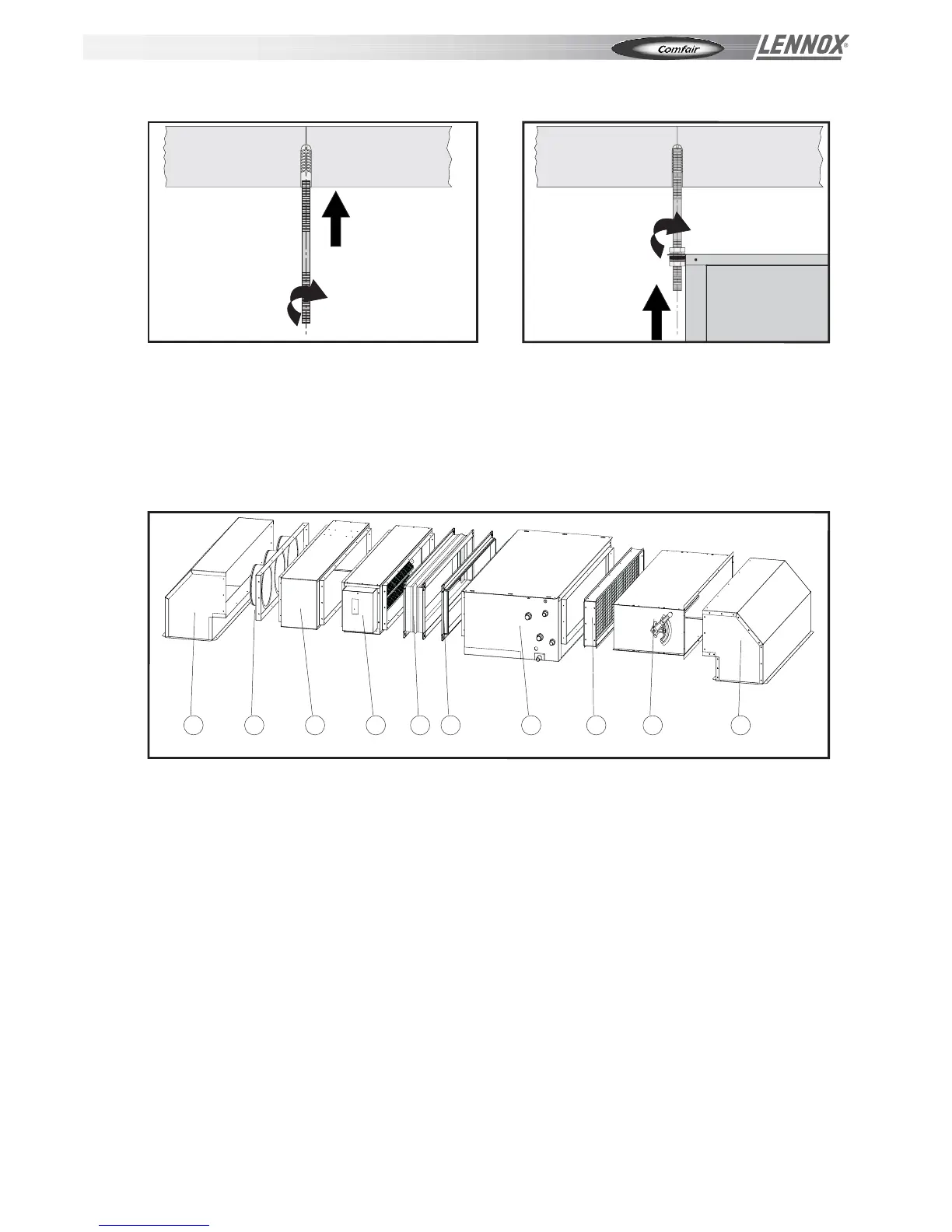
Fix the threaded rods of the correct length to the screw anchors (fig. 6) and insert them into the relative slots (fig. 7).
After having created a slope (max. 3 cm/m) in the direction of the condensate outlet, lock the threaded rod with a nut
and check nut. To prevent possible noise being created by vibrations from the unit, it is advisable to insert a vibration-
damping joint.
N.B.: the screw anchors, threaded rods and whatever else is necessary for accomplishing the installation are NOT
included in the supply of the air treatment unit.
INSTALLATION OF THE ACCESSORIES
LEGEND
1 RAM 90° intake/delivery plenum
2 BAM intake/delivery union with circular fittings
3 PAM straight intake/delivery plenum
4 SRE heating section (with electric heating element)
5 GAM vibration isolation joint
6 FAM connecting flange
7 UTC base unit
8 SFA air filter section
9 SSP section with external air intake (manual).
N.B.: Fig. 8 shows the exploded view of the unit with ALL the accessories.
Fig. 6
Fig. 7
1
2
3
4
5 6
7
8
9
1
Fig. 8
INSTALLATION - OPERATING & MAINTENANCE MANU
AL
Page 7
 Loading...