Page 29
On Board Links
Note: In communicating systems with a conventional out-
door unit (non-communicating), the on-board clippable
links must be set to properly congure the system.
WARNING
Carefully review all conguration information
provided. Failure to properly set DIP switches,
jumpers and on-board links can result in improper
operation!
On-Board Link W914 Dehum or Harmony (R to DS)
On-Board Link W914 Dehum or Harmony (R to DS) On-
board link W914, is a clippable connection between ter-
minals R and DS on the integrated control. W914 must
be cut when the furnace is installed with either the ZSV
variable zoning system control or a thermostat which fea-
tures humidity control. If the link is left intact the PMW sig-
nal from the ZSV control will be blocked and also lead to
control damage
Refer to TABLE 12 for operation sequence in applications
including EL296DFV, a thermostat which features humid-
ity control and a single-speed outdoor unit. TABLE 13
gives the operation sequence in applications with a two-
speed outdoor unit.
On-Board Link W951 Heat Pump (R to O)
On-board link W951 is a clippable connection between
terminals R and O on the integrated control. W951 must
be cut when the furnace is installed in applications which
include a heat pump unit and a thermostat which features
dual fuel use. If the link is left intact, terminal “O” will re-
main energized eliminating the HEAT MODE in the heat
pump.
On-Board Link W915 2 Stage Compr (Y1 to Y2)
On-board link W915 is a clippable connection between
terminals Y1 and Y2 on the integrated control. W915 must
be cut if two-stage cooling will be used. If the Y1 to Y2 link
is not cut the outdoor unit will operate in second-stage
cooling only.
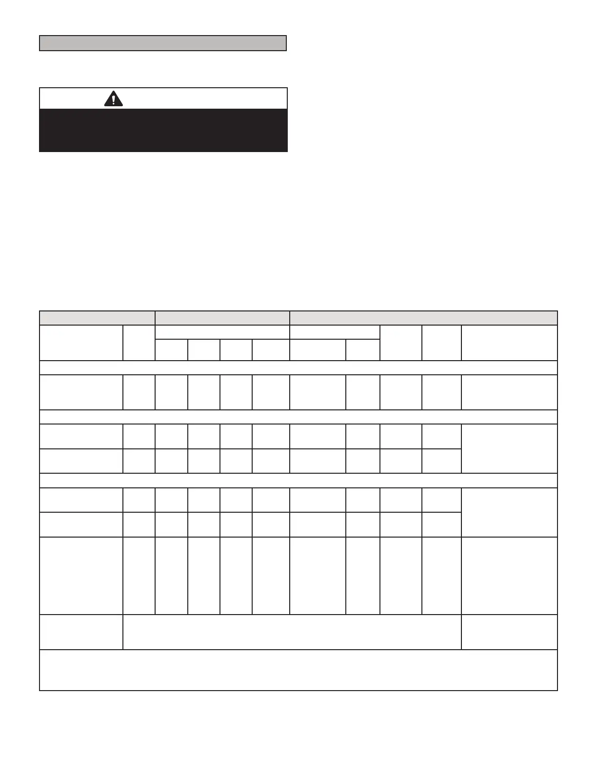
TABLE 12
OPERATING SEQUENCE
Non-Communicating Thermostat with Humidity Control Feature and Single-Speed Outdoor Unit
OPERATING SEQUENCE SYSTEM DEMAND SYSTEM RESPONSE
System
Condition
Step
Thermostat Demand Relative Humidity
Compre
ssor
Blower
CFM
(cool)
Comments
Y1 O G W1 Status D
NO CALL FOR DEHUMIDIFICATION
Normal Operation 1 On On On Acceptable
24
VAC
High 100%
Compressor and
indoor blower follow
thermostat demand
BASIC MODE (only active on a Y1 thermostat demand)
Normal Operation 1 On On On Acceptable
24
VAC
High 100%
CS7500 thermostat
energizes Y1 and de-
energizes D on a call
for de-humidication
Dehumidication
call
2 On On On Demand 0 VAC High 70%
PRECISION MODE (operates independent of a Y1 demand)
Normal Operation 1 On On On Acceptable
24
VAC
High 100%
Dehumidication
mode begins when
humidity is greater
than set point
Dehumidication
Call
2 On On On Demand 0 VAC High 70%
Dehumidication
Call Only
1 On On On Demand 0 VAC High 70%
CS7500 thermostat
will try to maintain
room humidity setpoint
by allowing the room
space to maintain
a cooler room
thermostat setpoint**
Jumpers at indoor unit with a single stage outdoor unit. With Condensing unit - Cut
W914 (R to DS) on SureLight
®
control With Heat Pump - Cut W914 (R to DS) &
W951 (R to O) on SureLight
®
control
Dave Lennox CS7500 thermostat to use for this application - Y2081 4 heat / 2 cool
*Dehumidication blower speed is 70% of COOL speed for all units .
**In Precision mode, CS7500 thermostat will maintain room temperature up to 2 °F (1.2°C) cooler than room setting.
 Loading...