Page 31
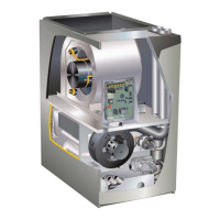
B- Indoor Blower Motor
Power Choke
(4 and 5 Ton Only)
Blower Motor
(B3)
To Remove Blower From Unit: Remove access panels,
Control box, Bolts and Wiring Jackplugs.
Then Slide Out Front of Unit.
FIGURE 7
WARNING
Disconnect power from unit and wait at
least ve minutes to allow capacitors to
discharge before attempting to service
motor. Failure to wait may cause personal
injury or death.
WARNING
During blower operation, the ECM motor emits
energy that may interfere with pacemaker operation.
Interference is reduced by both the sheet metal
cabinet and distance.
The motor communicates with the integrated control via
a 2-way serial connection. The motor receives all neces-
sary functional parameters from the integrated control and
does not rely on a factory program like traditional variable
speed motors. Units use a three-phase, electronically
controlled D.C. brushless motor (controller converts single
phase a.c. to three phase D.C.), with a permanent-magnet
type rotor (FIGURE 8). Because this motor has a perma-
nent magnet rotor it does not need brushes like conven-
tional D.C. motors.
The stator windings are split into three poles which are
electrically connected to the controller. This arrangement
allows motor windings to turn on and o in sequence by
the controller.
A solid-state controller is permanently attached to the mo-
tor. The controller is primarily an A.C. to D.C. converter.
Converted D.C. power is used to drive the motor. The con-
troller contains a microprocessor which monitors varying
conditions inside the motor (such as motor workload).
IMPORTANT
Earlier ECM motors used on other Lennox furnace
models are not interchangeable with motors used
on the EL296UH furnace line.
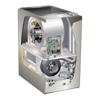
STATOR
(WINDINGS)
OUTPUT
SHAFT
BEARING
FIGURE 8
The controller uses sensing devices to sense what posi-
tion the rotor is in at any given time. By sensing the posi-
tion of the rotor and then switching the motor windings on
and o in sequence, the rotor shaft turns the blower.
All blower motors use single phase power. An external run
capacitor is not used. The motor uses permanently lubri-
cated ball-type bearings.
Internal Operation
The motor is controlled via serial communication between
the integrated control on the furnace and the controller
attached to the motor shell. The messages sent back and
forth between the two controls serve to communicate rota-
tional direction, demand, motor size, current draw, torque,
and rpm, among other variables.
Motor rpm is continually adjusted internally to maintain
constant static pressure against the blower wheel. The
controller monitors the static work load on the motor and
motor ampdraw to determine the amount of rpm adjust-
ment. Blower rpm may be adjusted any amount in order to
maintain a constant cfm as shown in Blower Ratings Ta-
bles. The cfm remains relatively stable over a broad range
of static pressure. Since the blower constantly adjusts rpm
to maintain a specied cfm, motor rpm is not rated. Hence,
the terms “cool speed”, “heat speed ” or “speed tap” in
this manual, on the unit wiring diagram and on blower B3,
refer to blower cfm regardless of motor rpm.
Initial Power Up
When line voltage is applied to B3, there will be a large
inrush of power lasting less than 1/4 second. This inrush
charges a bank of DC lter capacitors inside the controller.
If the disconnect switch is bounced when the disconnect is
closed, the disconnect contacts may become welded. Try
not to bounce the disconnect switch when applying power
to the unit.
 Loading...