Page 39
4 - Remove white PVC pipes, slide up and out thru the
top cap.
5 - Remove the black plastic tting in top cap which
previously aligned the PVC pipes.
6 - Remove the remaining parts of the pipe clamp at
the blower deck.
7 - Remove the sheet metal patch plate on the side
of the cabinet which covers the openings for side
venting option. Save screws for reuse.
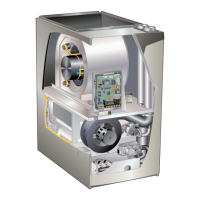
8 - Re-use the patch plate to cover the hole in the top
cap. See FIGURE 19. Remove the 2 screws which
secure the top cap to the furnace on the right side
and re-install securing the right edge of the patch
plate and the right side of the top cap to the furnace.
Use 2 self-drilling sheet metal screws (provided) to
nish securing the left edge of the patch plate on
the left side.
9 - Use a utility knife to cut out the cabinet insulation for
the right side vent / air intake.
10 - Install the two 90° street elbows (provided) through
the side of the cabinet. The male side of each
elbow should extend down through the blower deck
and connect to the rubber ttings below. Once the
elbows are properly positioned, tighten each clamp.
11 - Peel protective backing from side vent sealing
gaskets (2) and apply to side vent sealing plates (2)
as shown in FIGURE 20.
12 - - Install the side vent sealing plates and gaskets on
the exterior of the cabinet as shown in FIGURE
20. Secure with six mounting screws (four reused
and two provided from bag assembly). Holes are
pre-punched in the parts and cabinet, no drilling is
required.
13 - Install sheet metal screws (provided) to seal extra
two holes in cabinet not used with side vent clamps
IMPORTANT
Side vent sealing plates and side vent sealing
gaskets must be used when converting to right side
venting. Failure to use gaskets and plates may lead
to improper operation of unit.
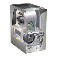
Exhaust/Air
Intake Connections
Pipe Clamp
Hose Clamp
FIGURE 18
Sheet Metal
Patch Plate
FIGURE 19
 Loading...