Page 60
8 - After assembly, wipe excess cement from pipe at end
of tting socket. A properly made joint will show a
bead around its entire perimeter. Any gaps may
indicate an improper assembly due to insucient
solvent.
9 - Handle joints carefully until completely set.
Venting Practices
* See Piping and Fittings Specifications table
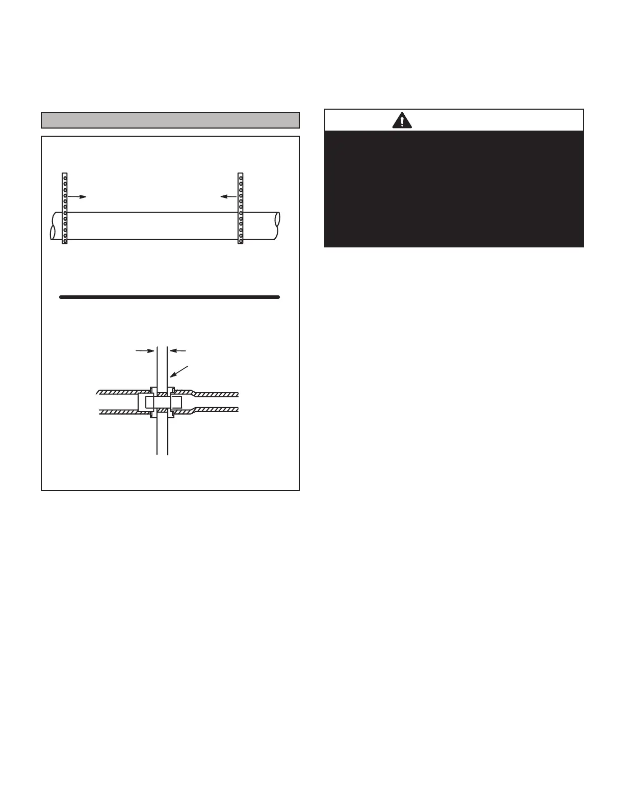
Piping Suspension Guidelines
NOTE - Isolate piping at the point where it exits the outside wall or
roof in order to prevent transmission of vibration to the structure.
SCHEDULE 40
PVC - 5'
all other pipe* - 3'
Wall
edistuoedisni
24” maximum
3/4” minimum
Wall Thickness Guidelines
FIGURE 19
1 - In areas where piping penetrates joists or interior
walls, hole must be large enough to allow clearance
on all sides of pipe through center of hole using a
hanger.
2 - When furnace is installed in a residence where unit
is shut down for an extended period of time, such
as a vacation home, make provisions for draining
condensate collection trap and lines.
Removal of the Furnace from Common Vent
In the event that an existing furnace is removed from a
venting system commonly run with separate gas applianc-
es, the venting system is likely to be too large to properly
vent the remaining attached appliances.
Conduct the following test while each appliance is oper-
ating and the other appliances (which are not operating)
remain connected to the common venting system. If the
venting system has been installed improperly, you must
correct the system as indicated in the general venting re-
quirements section.
WARNING
CARBON MONOXIDE POISONING HAZARD
Failure to follow the steps outlined below for each
appliance connected to the venting system being placed
into operation could result in carbon monoxide poisoning
or death.
The following steps shall be followed for each appliance
connected to the venting system being placed into
operation, while all other appliances connected to the
venting system are not in operation:
1 - Seal any unused openings in the common venting
system.
2 - Inspect the venting system for proper size and
horizontal pitch. Determine that there is no blockage,
restriction, leakage, corrosion, or other deciencies
which could cause an unsafe condition.
3 - Close all building doors and windows and all doors
between the space in which the appliances
remaining connected to the common venting system
are located and other spaces of the building. Turn on
clothes dryers and any appliances not connected to
the common venting system. Turn on any exhaust
fans, such as range hoods and bathroom exhausts,
so they will operate at maximum speed. Do not
operate a summer exhaust fan. Close replace
dampers.
4 - Follow the lighting instructions. Turn on the appliance
that is being inspected. Adjust the thermostat so
that the appliance operates continuously.
5 - After the main burner has operated for 5 minutes,
test for leaks of ue gases at the draft hood relief
opening. Use the ame of a match or candle.
6 - After determining that each appliance connected to
the common venting system is venting properly,
(step 3 return all doors, widows, exhaust fans,
replace dampers, and any other gas-burning
appliances to their previous mode of operation.
7 - If a venting problem is found during any of the
preceding tests, the common venting system must
be modied to correct the problem.
Resize the common venting system to the minimum
vent pipe size determined by using the appropriate
tables in Appendix G. (These are in the current stan-
dards)
 Loading...


