Page 14
Integrated Control DIP Switches
EL296UHE units are equipped with a two-stage integrat-
ed control. This control manages ignition timing, heating
mode fan o delays and indoor blower speeds based on
selections made using the control dip switches and jump-
ers.
The control includes an internal watchguard feature which
automatically resets the ignition control when it has been
locked out. After one hour of continuous thermostat de-
mand for heat, the watchguard will break and remake
thermostat demand to the furnace and automatically reset
the control to relight the furnace.
Heating Operation DIP Switch Settings
Switch 1 -- Thermostat Selection -- This unit may be
used with either a single-stage or two-stage thermostat.
The thermostat selection is made using a DIP switch
which must be properly positioned for the particular appli-
cation. The DIP switch is factory-positioned for use with a
twostage thermostat. If a single-stage thermostat is to be
used, the DIP switch must be repositioned.
a. Select “OFF” for two-stage heating operation controlled by
a two-stage heating thermostat (factory setting);
b. Select “ON” for two-stage heating operation controlled by
a single-stage heating thermostat. This setting
provides a timed delay before second-stage heat
is initiated.
Switch 2 --- Second Stage Delay (Used with Single-
Stage Thermostat Only) -- This switch is used to deter-
mine the second stage on delay when a single-stage ther-
mostat is being used. The switch is factory-set in the OFF
position, which provides a 7-minute delay before second-
stage heat is initiated. If the switch is toggled to the ON
position, it will provide a 12-minute delay before second-
stage heat is initiated. This switch is only activated when
the thermostat selector jumper is positioned for SINGLE-
stage thermostat use.
Indoor Blower Operation DIP Switch Settings
Switches 3 and 4 -- Heating Mode Blower-O Delay --
The blower-on delay of 30 seconds is not adjustable. The
blower-o delay (time that the blower operates after the
heating demand has been satised) can be adjusted by
moving switches 3 and 4 on the integrated control. The
unit is shipped from the factory with a blower-o delay of
90 seconds.
The blower o delay aects comfort and is adjustable to
satisfy individual applications. Adjust the blower o de-
lay to achieve a supply air temperature between 90° and
110°F at the exact moment that the blower is de-ener-
gized. Longer o delay settings provide lower supply air
temperatures; shorter settings provide higher supply air
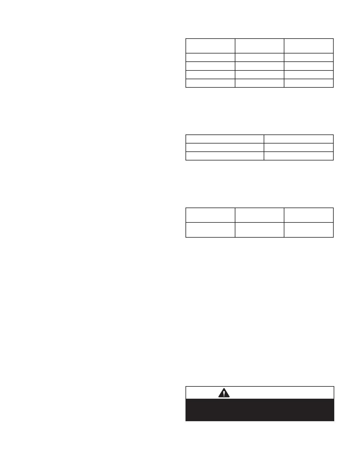
temperatures. Table 5 provides the blower o timings that
will result from dierent switch settings.
TABLE 5
Blower O Heating Mode Delay Switch Settings
Blower O Delay
Seconds
Switch 3 Switch 4
60 On O
90 (factory) O O
120 O On
180 On On
Switch 5 -- Cooling Mode Blower-O Delay-- The unit
is shipped from the factory with the dip switch positioned
OFF for a 45 second delay. Table 6 provides the cooling
mode o delay settings.
TABLE 6
Blower O Cooling Mode Delay Switch Settings
Blower O Delay Seconds Switch 5
45 (factory) O
2 On
Switches 6 and 7 -- Continuous Fan Mode -- Continu-
ous fan speed can be controlled by changing DIP switch
positions. Table 7 below provides DIP switch settings for
continuous fan mode.
TABLE 7
Continuous Fan Mode Settings
Continuous Fan
Mode
Switch 6 Switch 7
Low Heat Speed
(Factory Setting)
O O
On-Board Link W914 Dehum
On-board link W914, is a clippable connection between
terminals R and DS on the integrated control. W914 must
be cut when the furnace is installed with a thermostat
which features humidity control. If the link is not cut, termi-
nal “DS” will remain energized not allowing the blower to
reduce to low cool speed upon a call for dehumidication.
On-Board Link W951 Heat Pump (R to O)
On-board link W951 is a clippable connection between
terminals R and O on the integrated control. W951 must
be cut when the furnace is installed in applications which
include a heat pump unit and a thermostat which features
dual fuel use. If the link is left intact, terminal “O” will re-
main energized eliminating the HEAT MODE in the heat
pump.
On-Board Link W915 2 Stage Compr (Y1 to Y2)
On-board link W915 is a clippable connection between
terminals Y1 and Y2 on the integrated control. W915 must
be cut if two-stage cooling will be used. If the Y1 to Y2 link
is not cut the outdoor unit will operate in second-stage
cooling only.
IMPORTANT
If any onboard link is cut by mistake, install a jumper
across the corresponding terminals on the low
voltage terminal strip. Do not replace control.

 Loading...


