# 45464K003 Page 13
After gas piping is complete, carefully check all piping
connections (factory and field) for gas leaks. Use a leak
detecting solution or other preferred means. Some soaps
used for leak detection are corrosive to certain
metals. Carefully rinse piping thoroughly after leak
detection has been completed.
Electrical Wiring
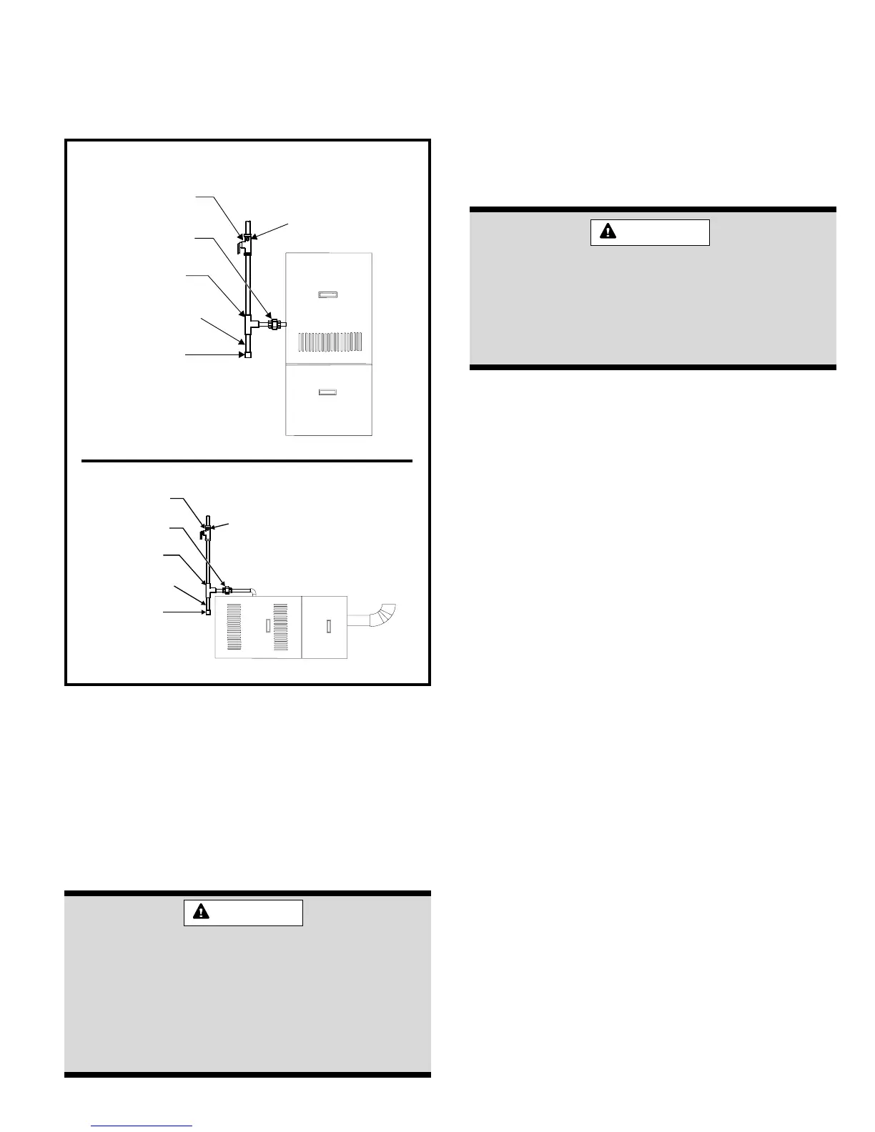
in the gas line, outside the unit, 5' above the floor, or in
accordance with any local codes. A test gauge connection
must be installed with a 1/8" NPT plugged tapping immedi-
ately upstream of the shutoff valve (see Figure 16).
The furnace must be isolated from the gas supply piping
system by closing the individual manual shutoff valve
during any pressure testing of the gas supply piping
system at test pressure equal to or less than 1/2 psig
(3.5 kPa) or 14" W.C. If the piping system is to be tested at
pressures in excess of 1/2 psig (3.5 kPa), the furnace and
its appliance main gas valve must be disconnected from
the gas supply piping system.
The gas valve supplied with this furnace is
rated at 1/2 psig maximum. Any higher pres-
sure may rupture the pressure regulator dia-
phragm and may cause overfiring of the burners
and improper burner operation. The overfiring
may result in the creation of carbon monoxide
which could cause asphyxiation.
WARNING
The furnace must be grounded and wired in accordance
with local codes or, in the absence of local codes, with the
National Electrical Code ANSI/NFPA No. 70 (latest edition)
and/or CSA C22.1 Electrical Code (latest edition) if an
external electrical source is utilized.
In all instances, other than wiring for the thermostat, the
wiring to be done and any replacement of wire shall
conform with the temperature limitation for Type T wire –
63°F (35°C) rise.
Connect a sufficiently sized wire with ground to the furnace’s
line voltage connections and ground lug. Refer to the
furnace rating plate for electrical characteristics to be used
in sizing field supply wiring and over-current protection.
The line voltage supply should be routed through a
readily accessible disconnect located within sight of the
furnace. A junction box on the furnace side panel is
provided for line voltage connections. Refer to the furnace
wiring diagram for specific connection information.
Proper polarity of the supply connections (“HOT”
and “NEUTRAL”) must be observed to ensure that
safety controls provide the protection intended.
A connection to the ground lug and actual earth ground
(typically a ground stake or buried steel pipe) must be
maintained for proper operation.
Thermostat
Install a room thermostat according to the instructions
furnished with it. Select a location on an inside wall that is
not subject to drafts, direct sunshine, or other heat
sources. The initial heat anticipator setting should be equal
to the total current draw of the control circuit.
Low voltage thermostat connections are to be made to the
blower control board as indicated on the wiring diagram.
Manual
Gas Valve
Union
Te e
Drip Leg
Cap
1/8" NPT
Plugged
Tapping
Gas Connection
Horizontal
Installation
Figure 16
Manual
Gas Valve
Union
Te e
Drip Leg
Cap
1/8" NPT
Plugged
Tapping
Upflow/
Counterflow
Installation
Risk of electrical shock. Disconnect electrical
power at the circuit breaker or service panel
before making electrical connections. Failure
to disconnect power supplies can result in
property damage, personal injury, or death.
WARNING
 Loading...


