Page 11
WARNING
Improper installation of the furnace can result in perĆ
sonal injury or death. Combustion and flue products
must never be allowed to enter the return air system
or the living space. Use screws and joint tape to seal
the return air system to the furnace.
In platform installations with bottom return air, the
furnace should be sealed airtight to the return air pleĆ
num. A door must never be used as a portion of the
return air duct system. The base must provide a
stable support and an airtight seal to the furnace. AlĆ
low absolutely no sagging, cracks, gaps, etc.
The return and supply air duct systems must never
be connected to or from other heating devices such
as a fireplace or stove, etc. Fire, explosion, carbon
monoxide poisoning, personal injury and/or properĆ
ty damage could result.
Duct System
Use industryĆapproved standards to size and install the
supply and return air duct system. This will result in a quiet
and lowĆstatic system that has uniform air distribution.
Supply Air Plenum
Furnaces installed without a cooling coil require the installaĆ
tion of a removable access panel in the supply air duct. The
access panel should be large enough to permit inspection (eiĆ
ther by smoke or reflected light) of the heat exchanger for
leaks after installation . The furnace access panel must alĆ
ways be in place when the furnace is operating and it must
not allow leaks into the supply air duct system.
Return Air Plenum
Return air must not be drawn from a room where this
furnace, or any other gas appliance (ie., a water heatĆ
er), is installed. When return air is drawn from a room,
a negative pressure is created in the room. If a gas apĆ
pliance is operating in a room with negative pressure, the
flue products can be pulled back down the vent pipe and
into the room. This reverse flow of the flue gas may result
in incomplete combustion and the formation of carbon
monoxide gas. This toxic gas might then be distributed
throughout the house by the furnace duct system.
In upflow applications, return air can be brought in through
the bottom or either side of the furnace. If a furnace with
bottom return air is installed on a platform, make an airtight
seal between the bottom of the furnace and the platform to
ensure proper and safe operation. Use fiberglass sealing
strips between the plenum and the furnace cabinet to enĆ
sure a tight seal. If a filter is installed, size the return air duct
to fit the filter frame.
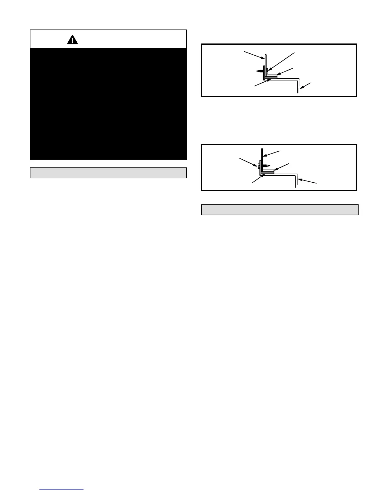
In downflow applications, use the following steps when instalĆ
ling return air plenum:
1 - Flange bottom edge of plenum with a hemmed edge.
See figure 12.
2 - Use fiberglass sealing strips between plenum and the
unit cabinet to ensure a tight seal.
3 - In all cases, secure the plenum to the top flanges of the
furnace using sheet metal screws. See figure 12.
SECURE
HEMMED EDGE
PLENUM
CABINET
SIDE PANEL
FIBERGLASS
SEALING STRIP
FIGURE 12
4 - In closet installations, it may be necessary to install
sheet metal screws from the inside. If this is the case,
make plenum with a removable front to install screws
as shown in figure 13.
SECURE FROM
INSIDE
HEMMED EDGE
FIBERGLASS
SEALING STRIP
CABINET
SIDE PANEL
PLENUM
FIGURE 13
Venting
A vent adapter is supplied with the furnace. It must be
installed between the induced draft blower flue outlet and
the vent connector using one or two corrosion-resistant
sheet metal screws. Modification of, or failure to install,
the adapter will cause unsafe unit operation and will
void A.G.A. and C.G.A. unit certification. The vent conĆ
nector does not require insulation.
The G24M series units are classified as fan-assisted CateĆ
gory I furnaces when vertically vented according to the latest
edition of ANSI Z21.47 Central Furnace Standard in the
USA and the current standards of CAN/CGA B149.1 and
B149.2 of the Natural Gas and Propane Installation Code in
Canada. A fan-assisted Category I furnace is an appliance
equipped with an integral mechanical means to either draw
or force products of combustion through the combustion
chamber and/or heat exchanger.
NOTE - Use these instructions as a guide. They do not suĆ
persede local codes.
The vent sizing tables in this manual were extracted from
the National Fuel Gas Code (NFPA 54 / ANSI Z223.1) and
are provided as a guide for proper vent installation. Proper
application, termination, construction and location of vents
must conform to local codes having jurisdiction. In the abĆ
sence of local codes, the NFGC serves as the defining docĆ
ument.
Refer to the tables and the venting information contained in
these instructions to properly size and install the venting
system.
Install first vent connector elbow a minimum of 6 in.
(152mm) from furnace vent outlet.

 Loading...


