Page 10
2 - After opening is cut, set the additive base into opening.
3 - Check fiberglass strips on additive base to make sure
they are properly glued and positioned.
4 - Lower supply air plenum into additive base until pleĆ
num flanges seal against fiberglass strips.
5 - Set unit on additive base so unit flanges drop into pleĆ
num. Refer to figure 8.
NOTE-Be careful not to damage fiberglass strips.
Check for tight seal.
C-Installation on Cooling Cabinet
1 - Refer to reverseĆflow coil installation instructions for
correctly sized opening in floor and installation of cabiĆ
net.
2 - When cooling cabinet is in place, install furnace so
flanges drop inside cabinet opening.
3 - Seal cabinet and check for air leakage.
Horizontal Applications
The Lennox G24M furnace can be installed in horizontal
applications in either upflow or downflow configuration
(See figure 6). It is preferable to install the furnace in the
standard upflow configuration, if possible, because the
vent pipe will not interfere with service access for the blowĆ
er. Install two #10 screws in the cabinet bottom (upflow conĆ
figuration) or cabinet top (downflow configuration) to proĆ
vide a better air seal. Do not install the furnace on its
back.
Horizontal Application
Installation Clearances
Vent
Connector
Type
Type C
Type B1
TOP 00
*FRONT 2 in. (51 mm) 2 in. (51 mm)
BACK 00
SIDES 2 in. (51 mm) 2 in. (51 mm)
VENT
6 in. (152 mm)
1 in. (25 mm)
FLOOR 0** 0**
*Front clearance in alcove installation must be 24 in.
(610 mm). Maintain a minimum of 24 in. (610 mm) for
front service access.
** For installations on a combustible floor, do not install
the furnace directly on carpeting, tile or other combusĆ
tible materials other than wood flooring.
BOTTOM
TOP
RIGHT
SIDE
LEFT
SIDE
FIGURE 9
Allow for clearances to combustible materials as indicated
on the unit rating plate. Minimum clearances for closet or
alcove installations are shown in figure 9.
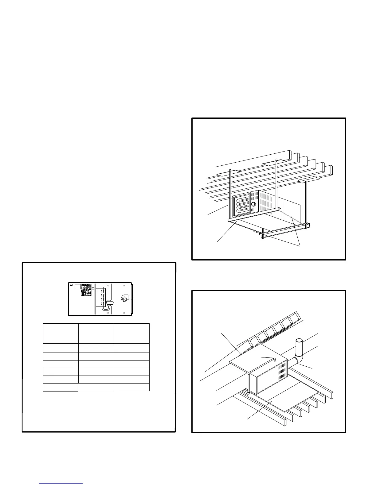
Furnaces may be installed in either an attic or a crawlĆ
space. Either suspend the furnace from roof rafters or floor
joists, as shown in figure 10, or install the furnace on a platĆ
form, as shown in figure 11.
NOTE - When the furnace is installed on a platform in a
crawlspace, it must be elevated enough to avoid water
damage and to allow the air conditioning coil to drain.
Horizontal Application
Unit Suspended in Attic or Crawlspace
1/4 in. ROD
ANGLE
IRON
SUPPORT TIES TO
PREVENT SPREADING
Leave sufficient clearance between rod and unit to
remove access panel.
FIGURE 10
Horizontal Application
Unit Installed on Platform
WORKING
PLATFORM
GAS
ENTRY
VENT
PIPE
NOTE - Line contact is perĆ
missible. See the unit rating
plate for clearances.
FIGURE 11

 Loading...


